Home › Vehicle Interior › METER / GAUGE / DISPLAY › METER / GAUGE SYSTEM
RM27L0U _58 Vehicle Interior _049339 METER / GAUGE / DISPLAY _0235844 METER / GAUGE SYSTEM J

METER / GAUGE / DISPLAY  METER / GAUGE SYSTEM  Accessory Meter does not Illuminate  


DESCRIPTION

·

This circuit provides power to the accessory meter.

·

The cruise information display of the accessory meter shows the vehicle information input into the combination meter. The display can be changed by using the drive monitor switch.


WIRING DIAGRAM
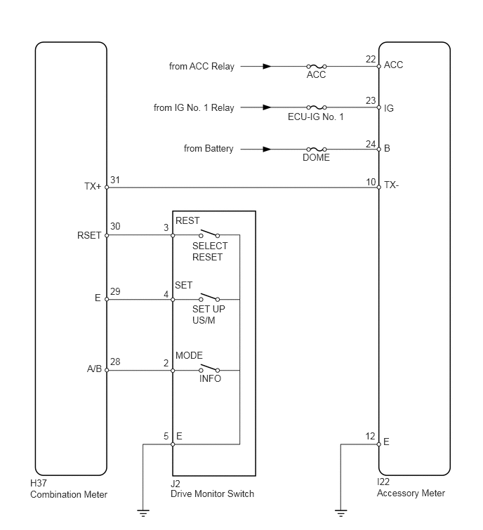
E163635E03
2.51,0.896 3.542,1.115 1.031,0.219 10 false from ACC Relay 4.552,1.021 4.865,1.219 0.313,0.198 10 false ACC 5.698,0.875 6.073,1.073 0.375,0.198 10 false ACC 5.698,2.656 6.073,2.854 0.375,0.198 10 false TX- 1.25,2.677 1.531,2.875 0.281,0.198 10 false TX+ 5.698,2.115 6.073,2.313 0.375,0.198 10 false B 5.698,1.521 6.073,1.719 0.375,0.198 10 false IG 5.427,0.792 5.625,0.99 0.198,0.198 10 false 22 5.427,1.406 5.625,1.604 0.198,0.198 10 false 23 5.427,2.052 5.625,2.25 0.198,0.198 10 false 24 5.427,2.615 5.625,2.813 0.198,0.198 10 false 10 1.635,2.583 1.833,2.781 0.198,0.198 10 false 31 1.635,3.271 1.833,3.469 0.198,0.198 10 false 30 2.427,3.292 2.594,3.49 0.167,0.198 10 false 3 2.604,3.188 3.094,3.385 0.49,0.198 10 false REST 1.146,3.406 1.542,3.604 0.396,0.198 10 false RSET 1.292,5.385 1.615,5.583 0.323,0.198 10 false A/B 1.406,4.333 1.542,4.531 0.135,0.198 10 false E 2.594,4.146 3.083,4.344 0.49,0.198 10 false SET 2.854,3.563 3.448,3.948 0.594,0.385 10 false SELECT RESET 2.854,4.5 3.448,4.885 0.594,0.385 10 false SET UP US/M 2.958,5.531 3.396,5.708 0.438,0.177 10 false INFO 2.427,4.281 2.594,4.479 0.167,0.198 10 false 4 2.427,5.302 2.594,5.5 0.167,0.198 10 false 2 2.604,5.188 3.063,5.385 0.458,0.198 10 false MODE 2.427,6.385 2.594,6.583 0.167,0.198 10 false 5 2.615,6.385 2.781,6.583 0.167,0.198 10 false E 5.417,6.385 5.667,6.583 0.25,0.198 10 false 12 5.688,6.469 5.854,6.667 0.167,0.198 10 false E 2.531,7.094 2.854,7.292 0.323,0.198 10 false J2 2.531,7.24 3.958,7.438 1.427,0.198 10 false Drive Monitor Switch 0.448,7.083 0.771,7.281 0.323,0.198 10 false H37 0.448,7.25 1.875,7.448 1.427,0.198 10 false Combination Meter 5.594,7.063 5.802,7.24 0.208,0.177 10 false I22 5.594,7.229 6.76,7.427 1.167,0.198 10 false Accessory Meter 1.635,4.24 1.833,4.438 0.198,0.198 10 false 29 1.635,5.281 1.833,5.479 0.198,0.198 10 false 28 4.271,1.646 5.167,1.823 0.896,0.177 10 false ECU-IG No. 1 4.49,2.25 4.938,2.438 0.448,0.188 10 false DOME 2.281,1.51 3.531,1.719 1.25,0.208 10 false from IG No. 1 Relay 2.729,2.115 3.563,2.313 0.833,0.198 10 false from Battery

PROCEDURE

1.CHECK ACCESSORY METER ASSEMBLY
a.

Check the malfunction of the accessory meter.

Result
Result Proceed to
Accessory meter does not display at all A
Cruise information display does not change B


A

2.INSPECT FUSE (DOME, ECU-IG NO. 1, ACC)

B

6.INSPECT DRIVE MONITOR SWITCH
2.INSPECT FUSE (DOME, ECU-IG NO. 1, ACC)
a.

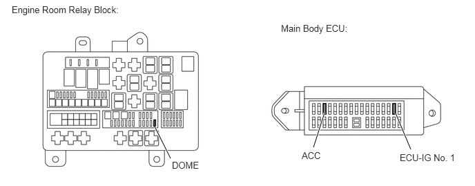
Remove the DOME fuse from the engine room relay block.
E345049E01
2.333,1.906 2.573,2.385 true 5.969,1.708 6.198,2.25 true 4.896,1.698 4.729,2.219 true 0.177,0.063 1.844,0.25 1.667,0.188 10 false Engine Room Relay Block: 4.24,0.344 5.292,0.521 1.052,0.177 10 false Main Body ECU: 2.594,2.406 3.031,2.573 0.438,0.167 10 false DOME 6.031,2.292 6.885,2.479 0.854,0.188 10 false ECU-IG No. 1 4.552,2.26 4.906,2.448 0.354,0.188 10 false ACC


b.

Remove the ECU-IG No. 1 and ACC fuses from the main body ECU.


c.

Measure the resistance according to the value(s) in the table below.

Standard Resistance:
Tester Connection Condition Specified Condition
DOME fuse Always Below 1 Ω
ECU-IG No. 1 fuse Always Below 1 Ω
ACC fuse Always Below 1 Ω


OK

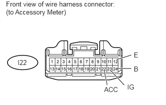
3.CHECK HARNESS AND CONNECTOR (ACCESSORY METER - BATTERY AND BODY GROUND)

NG

CHECK FOR SHORTS IN ALL HARNESSES AND CONNECTORS CONNECTED TO FUSE AND REPLACE FUSE

3.CHECK HARNESS AND CONNECTOR (ACCESSORY METER - BATTERY AND BODY GROUND)
a.
U153997E02
2.417,1.24 2.719,1.146 true 2.427,1.427 2.719,1.427 true 2.281,1.458 2.573,1.771 true 2.156,1.469 2.219,1.771 true 0.125,0 2.469,0.344 2.344,0.344 10 false Front view of wire harness connector: (to Accessory Meter) 2.771,1.354 2.896,1.5 0.125,0.146 10 false B 2.635,1.729 2.813,1.875 0.177,0.146 10 false IG 2.156,1.781 2.479,1.938 0.323,0.156 10 false ACC 2.771,1.063 2.896,1.208 0.125,0.146 10 false E 0.365,1.219 0.583,1.375 0.219,0.156 10 false I22

Disconnect the I22 accessory meter connector.


b.

Measure the voltage according to the value(s) in the table below.

Standard Voltage:
Tester Connection Switch Condition Specified Condition
I22-22 (ACC) - Body ground Ignition switch ACC 11 to 14 V
I22-23 (IG) - Body ground Ignition switch ON 11 to 14 V
I22-24 (B) - Body ground Always 11 to 14 V


c.

Measure the resistance according to the value(s) in the table below.

Standard Resistance:
Tester Connection Condition Specified Condition
I22-12 (E) - Body ground Always Below 1 Ω


OK

4.REPLACE ACCESSORY METER ASSEMBLY

NG

REPAIR OR REPLACE HARNESS OR CONNECTOR

4.REPLACE ACCESSORY METER ASSEMBLY
a.

Temporarily replace the accessory meter with a new or normally functioning one (See page Vehicle Interior>METER / GAUGE / DISPLAY>ACCESSORY METER>REMOVAL).


NEXT

5.CHECK ACCESSORY METER ASSEMBLY (OPERATION)
a.

Check that the accessory meter operation is normal.

OK:

Operation of accessory meter returns to normal.


OK

END (ACCESSORY METER IS DEFECTIVE)

NG

REPLACE COMBINATION METER ASSEMBLY

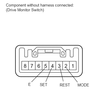
6.INSPECT DRIVE MONITOR SWITCH
a.
E146702E05
2.104,2.385 2.219,2.854 false 1.813,2.375 1.604,2.865 false 2.333,2.396 2.719,2.885 false 1.573,2.396 1.104,2.875 false 0.208,0.094 2.708,0.458 2.5,0.365 10 false Component without harness connected: (Drive Monitor Switch) 2.719,2.896 3.167,3.063 0.448,0.167 10 false MODE 1.396,2.885 1.688,3.052 0.292,0.167 10 false SET 2.094,2.896 2.5,3.063 0.406,0.167 10 false REST 0.99,2.875 1.104,3.042 0.115,0.167 10 false E

Remove the drive monitor switch (See page Vehicle Interior>METER / GAUGE / DISPLAY>DRIVE MONITOR SWITCH>REMOVAL).


b.

Measure the resistance according to the value(s) in the table below.

Standard Resistance:
Tester Connection Switch Condition Specified Condition
2 (MODE) - 5 (E) INFO switch pressed Below 1 Ω
INFO switch not pressed 10 kΩ or higher
3 (REST) - 5 (E) SELECT switch pressed Below 1 Ω
SELECT switch not pressed 10 kΩ or higher
4 (SET) - 5 (E) SETUP switch pressed Below 1 Ω
SETUP switch not pressed 10 kΩ or higher


OK

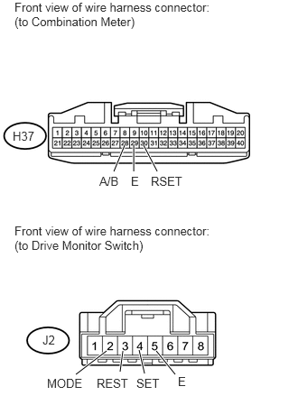
7.CHECK HARNESS AND CONNECTOR (DRIVE MONITOR SWITCH - COMBINATION METER AND BODY GROUND)

NG

7.CHECK HARNESS AND CONNECTOR (DRIVE MONITOR SWITCH - COMBINATION METER AND BODY GROUND)
a.
U153998E02
1.438,1.677 1.313,1.979 true 1.542,1.677 1.542,1.979 true 1.656,1.677 1.813,1.979 true 1.417,4.052 1.385,4.292 true 1.229,4.052 0.875,4.323 true 1.604,4.042 1.667,4.313 true 1.802,4.052 2.021,4.323 true 0.167,0 2.521,0.344 2.354,0.344 10 false Front view of wire harness connector: (to Combination Meter) 1.146,2.01 1.406,2.167 0.26,0.156 10 false A/B 1.51,2.01 1.646,2.167 0.135,0.156 10 false E 1.74,2.01 2.156,2.167 0.417,0.156 10 false RSET 0.167,2.583 2.521,2.927 2.354,0.344 10 false Front view of wire harness connector: (to Drive Monitor Switch) 1.573,4.344 1.875,4.5 0.302,0.156 10 false SET 2.052,4.323 2.188,4.479 0.135,0.156 10 false E 0.542,4.344 0.99,4.5 0.448,0.156 10 false MODE 1.115,4.344 1.531,4.5 0.417,0.156 10 false REST 0.146,1.49 0.427,1.635 0.281,0.146 10 false H37 0.49,3.844 0.667,3.99 0.177,0.146 10 false J2

Disconnect the H37 combination meter connector.


b.

Disconnect the J2 drive monitor switch connector.


c.

Measure the resistance according to the value(s) in the table below.

Standard Resistance:
Tester Connection Condition Specified Condition
H37-28 (A/B) - J2-2 (MODE) Always Below 1 Ω
H37-28 (A/B) - Body ground Always 10 kΩ or higher
H37-29 (E) - J2-4 (SET) Always Below 1 Ω
H37-29 (E) - Body ground Always 10 kΩ or higher
H37-30 (RSET) - J2-3 (REST) Always Below 1 Ω
H37-30 (RSET) - Body ground Always 10 kΩ or higher
J2-5 (E) - Body ground Always Below 1 Ω


OK

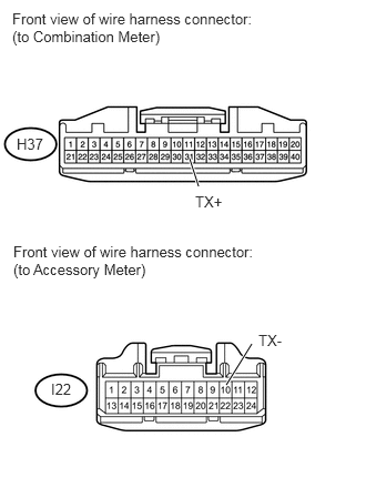
8.CHECK HARNESS AND CONNECTOR (COMBINATION METER - ACCESSORY METER)

NG

REPAIR OR REPLACE HARNESS OR CONNECTOR

8.CHECK HARNESS AND CONNECTOR (COMBINATION METER - ACCESSORY METER)
a.
U154000E02
1.781,1.49 1.865,1.75 true 2.125,3.615 2.365,3.229 true 0.115,0.094 2.448,0.448 2.333,0.354 10 false Front view of wire harness connector: (to Combination Meter) 0.156,1.271 0.427,1.417 0.271,0.146 10 false H37 1.833,1.813 2.125,1.958 0.292,0.146 10 false TX+ 0.125,2.281 2.458,2.635 2.333,0.354 10 false Front view of wire harness connector: (to Accessory Meter) 0.479,3.573 0.698,3.719 0.219,0.146 10 false I22 2.427,3.115 2.719,3.26 0.292,0.146 10 false TX-

Disconnect the H37 combination meter connector.


b.

Disconnect the I22 accessory meter connector.


c.

Measure the resistance according to the value(s) in the table below.

Standard Resistance:
Tester Connection Condition Specified Condition
H37-31 (TX+) - I22-10 (TX-) Always Below 1 Ω
H37-31 (TX+) - Body ground Always 10 kΩ or higher


OK

9.REPLACE ACCESSORY METER ASSEMBLY

NG

REPAIR OR REPLACE HARNESS OR CONNECTOR

9.REPLACE ACCESSORY METER ASSEMBLY
a.

Temporarily replace the accessory meter with a new or normally functioning one (See page Vehicle Interior>METER / GAUGE / DISPLAY>ACCESSORY METER>REMOVAL).


NEXT

10.CHECK ACCESSORY METER ASSEMBLY (OPERATION)
a.

Check that the accessory meter operation is normal.

OK:

Operation of accessory meter returns to normal.


OK

END (ACCESSORY METER IS DEFECTIVE)

NG

REPLACE COMBINATION METER ASSEMBLY