RM27L0U
_58
Vehicle Interior
_049342
SEAT
_0235877
FRONT POWER SEAT CONTROL SYSTEM(w/ Memory)
J
SEAT FRONT POWER SEAT CONTROL SYSTEM(w/ Memory) Front Power Seat does not Operate with Front Power Seat Switch
DESCRIPTION
When a signal is input into the position control ECU, the ECU manages the signals received from the front power seat switch LH, and operates each motor. When 2 or more signals are input, the motors only operate when the signals are from the slide switch and reclining switch.
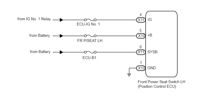
WIRING DIAGRAM
2.75,0.781 3.646,0.979
0.896,0.198
10
false
ECU-IG No. 1
2.771,1.375 3.719,1.552
0.948,0.177
10
false
FR P/SEAT LH
2.958,1.99 3.5,2.156
0.542,0.167
10
false
ECU-B1
5.281,2.354 5.625,2.531
0.344,0.177
10
false
GND
5.292,0.615 5.479,0.781
0.188,0.167
10
false
IG
5.281,1.177 5.5,1.354
0.219,0.177
10
false
+B
5.281,1.781 5.719,1.948
0.438,0.167
10
false
SYSB
4.938,2.854 6.771,3.271
1.833,0.417
10
false
Front Power Seat Switch LH (Position Control ECU)
5.01,2.167 5.135,2.323
0.125,0.156
10
false
1
5,0.438 5.135,0.604
0.135,0.167
10
false
4
5,1.01 5.104,1.188
0.104,0.177
10
false
5
5,1.604 5.115,1.76
0.115,0.156
10
false
8
0.625,0.594 1.865,0.771
1.24,0.177
10
false
from IG No. 1 Relay
1.052,1.188 1.854,1.385
0.802,0.198
10
false
from Battery
1.073,1.771 1.885,1.979
0.813,0.208
10
false
from Battery
4.948,2.365 5.208,2.542
0.26,0.177
10
false
X10
4.948,1.198 5.198,1.375
0.25,0.177
10
false
X10
4.938,1.781 5.188,1.948
0.25,0.167
10
false
X11
4.938,0.625 5.167,0.813
0.229,0.188
10
false
X11
PROCEDURE
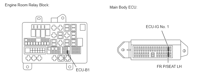
1.INSPECT FUSE (ECU-B1, ECU-IG No. 1, FR P/SEAT LH)
a.
Remove the ECU-B1 fuse from the engine room relay block.
2.76,2.438 2.438,1.927
false
6.094,1.719 5.854,1.115
true
6.083,2.281 6.083,2.063
true
0.177,0.094 1.844,0.281
1.667,0.188
10
false
Engine Room Relay Block:
3.969,0.177 5.031,0.365
1.063,0.188
10
false
Main Body ECU:
2.75,2.458 3.26,2.635
0.51,0.177
10
false
ECU-B1
5.281,0.885 6.156,1.083
0.875,0.198
10
false
ECU-IG No. 1
5.677,2.333 6.635,2.521
0.958,0.188
10
false
FR P/SEAT LH
b.
Remove the ECU-IG No. 1 and FR P/SEAT LH fuses from the main body ECU.
c.
Measure the resistance according to the value(s) in the table below.
- Standard Resistance:
Tester Connection Condition Specified Condition ECU-B1 fuse Always Below 1 Ω ECU-IG No. 1 fuse Always Below 1 Ω FR P/SEAT LH fuse Always Below 1 Ω
OK
2.CHECK HARNESS AND CONNECTOR (FRONT POWER SEAT SWITCH LH - BATTERY AND BODY GROUND)
NG
CHECK FOR SHORTS IN ALL HARNESSES AND CONNECTORS CONNECTED TO FUSE AND REPLACE FUSE
2.CHECK HARNESS AND CONNECTOR (FRONT POWER SEAT SWITCH LH - BATTERY AND BODY GROUND)
a.
1.365,3.833 1.125,3.927
true
1.375,3.583 1.125,3.427
true
2.083,1.688 2.344,1.792
true
2.073,1.479 2.333,1.365
true
0.135,0.063 2.51,0.448
2.375,0.385
10
false
Front view of wire harness connector: (to Front Power Seat Switch LH)
0.125,2.385 2.5,2.771
2.375,0.385
10
false
Front view of wire harness connector: (to Front Power Seat Switch LH)
2.375,1.26 2.698,1.479
0.323,0.219
10
false
IG
2.365,1.729 2.896,1.958
0.531,0.229
10
false
SYSB
0.76,3.344 1.115,3.5
0.354,0.156
10
false
GND
0.885,3.854 1.083,4.021
0.198,0.167
10
false
+B
0.646,1.417 0.906,1.583
0.26,0.167
10
false
X11
0.281,3.656 0.542,3.833
0.26,0.177
10
false
X10
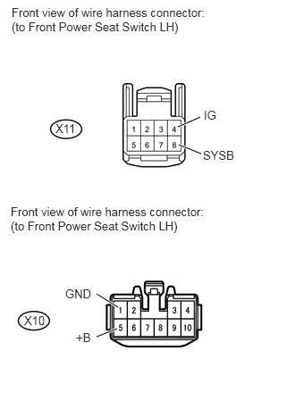
Disconnect the X10 and X11 switch connectors.
b.
Measure the voltage according to the value(s) in the table below.
- Standard Voltage:
Tester Connection Condition Specified Condition X10-5 (+B) - Body ground Always 11 to 14 V X11-4 (IG) - Body ground Ignition switch off Below 1 V Ignition switch ON 11 to 14 V X11-8 (SYSB) - Body ground Always 11 to 14 V
c.
Measure the resistance according to the value(s) in the table below.
- Standard Resistance:
Tester Connection Condition Specified Condition X10-1 (GND) - Body ground Always Below 1 Ω
OK
REPLACE FRONT POWER SEAT SWITCH LH
NG
REPAIR OR REPLACE HARNESS OR CONNECTOR