Home › Vehicle Interior › SEAT › REAR POWER SEAT CONTROL SYSTEM
RM27L0U _58 Vehicle Interior _049342 SEAT _0235879 REAR POWER SEAT CONTROL SYSTEM J

SEAT  REAR POWER SEAT CONTROL SYSTEM  Position Sensor Circuit  


DESCRIPTION

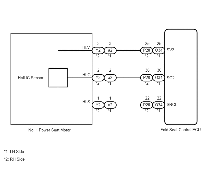
The fold seat control ECU receives switch operation signals from the rear power seat switch and fold seat switch, and activates the power seat motor. At this time, the Hall IC (seatback position sensor) detects the actuation of the seatback and sends a seatback actuation signal to the fold seat control ECU. The fold seat control ECU uses signals from the Hall IC (seatback position sensor) to detect if an object is caught or if any other abnormal condition has occurred.

WIRING DIAGRAM
B193762E02
0.613,2.585 2.055,3.287 1.442,0.702 10 Hall IC Sensor 5.506,4.368 6.973,4.924 1.467,0.555 10 Fold Seat Control ECU 0.973,4.38 2.956,4.869 1.984,0.489 10 No. 1 Power Seat Motor 3.282,3.511 3.632,3.713 0.350,0.202 10 Y2 3.282,2.573 3.632,2.775 0.350,0.202 10 Y2 3.703,3.511 4.053,3.713 0.350,0.202 10 a2 3.703,2.573 4.053,2.775 0.350,0.202 10 a2 5.314,3.511 5.664,3.713 0.350,0.202 10 O34 4.908,3.511 5.258,3.713 0.350,0.202 10 P20 5.314,2.573 5.664,2.775 0.350,0.202 10 O34 4.908,2.573 5.258,2.775 0.350,0.202 10 P20 5.314,1.634 5.664,1.836 0.350,0.202 10 O34 4.908,1.634 5.258,1.836 0.350,0.202 10 P20 3.703,1.634 4.053,1.836 0.350,0.202 10 a2 3.282,1.634 3.632,1.836 0.350,0.202 10 Y2 5.715,1.628 6.175,1.852 0.461,0.224 10 SV2 5.715,2.581 6.175,2.805 0.461,0.224 10 SG2 5.715,3.505 6.175,3.730 0.461,0.224 10 SRCL 3.284,3.714 3.512,3.905 0.228,0.191 10 *2 3.69,3.714 3.918,3.905 0.228,0.191 10 *1 3.284,2.775 3.512,2.966 0.228,0.191 10 *2 3.69,2.775 3.918,2.966 0.228,0.191 10 *1 3.284,1.837 3.512,2.027 0.228,0.191 10 *2 3.69,1.837 3.918,2.027 0.228,0.191 10 *1 4.965,3.714 5.193,3.905 0.228,0.191 10 *2 5.371,3.714 5.599,3.905 0.228,0.191 10 *1 4.965,2.775 5.193,2.966 0.228,0.191 10 *2 5.371,2.775 5.599,2.966 0.228,0.191 10 *1 4.965,1.837 5.193,2.027 0.228,0.191 10 *2 5.371,1.837 5.599,2.027 0.228,0.191 10 *1 2.825,3.403 3.180,3.582 0.355,0.179 10 HLS 2.825,2.478 3.180,2.657 0.355,0.179 10 HLG 2.825,1.539 3.180,1.719 0.355,0.179 10 HLV 3.336,2.326 3.621,2.529 0.285,0.202 10 2 3.336,3.279 3.621,3.482 0.285,0.202 10 1 3.336,1.402 3.621,1.604 0.285,0.202 10 3 3.743,2.326 4.027,2.529 0.285,0.202 10 2 3.743,3.279 4.027,3.482 0.285,0.202 10 1 3.743,1.402 4.027,1.604 0.285,0.202 10 3 4.976,2.326 5.260,2.529 0.285,0.202 10 36 4.976,3.279 5.260,3.482 0.285,0.202 10 22 4.976,1.402 5.260,1.604 0.285,0.202 10 25 5.382,2.326 5.667,2.529 0.285,0.202 10 36 5.382,3.279 5.667,3.482 0.285,0.202 10 22 5.382,1.402 5.667,1.604 0.285,0.202 10 25 0.137,5.113 0.904,5.282 0.767,0.170 10 *1: LH Side 0.137,5.376 0.904,5.546 0.767,0.170 10 *2: RH Side

PROCEDURE

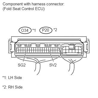
1.CHECK FOLD SEAT CONTROL ECU (SV2 TERMINAL)
a.
U153326E02
0.917,1.802 0.813,2.156 true 1.729,1.792 1.875,2.156 true 0.094,0.052 2.375,0.646 2.281,0.594 10 false Component with harness connector: (Fold Seat Control ECU) 1.479,0.969 1.74,1.146 0.26,0.177 10 false P20 0.74,0.979 1.021,1.156 0.281,0.177 10 false O34 0.625,2.198 0.927,2.375 0.302,0.177 10 false SG2 1.729,2.198 2.021,2.375 0.292,0.177 10 false SV2 1.135,0.979 1.302,1.115 0.167,0.135 10 false *1 1.875,0.958 2.042,1.146 0.167,0.188 10 false *2 0.083,2.969 0.99,3.156 0.906,0.188 10 false *2: RH Side 0.083,2.635 0.99,2.823 0.906,0.188 10 false *1: LH Side

Measure the voltage according to the value(s) in the table below.

Standard Voltage:
LH Side
Tester Connection Condition Specified Condition
O34-25 (SV2) - O34-36 (SG2) Back door open 11 to 14 V

RH Side
Tester Connection Condition Specified Condition
P20-25 (SV2) - P20-36 (SG2) Back door open 11 to 14 V


OK

2.CHECK FOLD SEAT CONTROL ECU (POSITION SENSOR SIGNAL)

NG

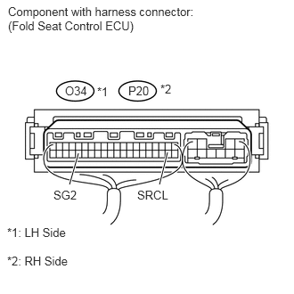
2.CHECK FOLD SEAT CONTROL ECU (POSITION SENSOR SIGNAL)
a.
U153327E02
1.958,1.781 1.865,2.156 true 0.917,1.792 0.813,2.156 true 0.094,0.052 2.375,0.646 2.281,0.594 10 false Component with harness connector: (Fold Seat Control ECU) 1.5,0.979 1.76,1.156 0.26,0.177 10 false P20 0.76,0.979 1.042,1.156 0.281,0.177 10 false O34 1.604,2.198 2.042,2.375 0.438,0.177 10 false SRCL 0.625,2.198 0.927,2.375 0.302,0.177 10 false SG2 1.135,0.99 1.302,1.125 0.167,0.135 10 false *1 1.875,0.958 2.042,1.146 0.167,0.188 10 false *2 0.083,2.969 0.99,3.156 0.906,0.188 10 false *2: RH Side 0.083,2.635 0.99,2.823 0.906,0.188 10 false *1: LH Side

Measure the voltage according to the value(s) in the table below.

Standard Voltage:
LH Side
Tester Connection Condition Specified Condition
O34-22 (SRCL) - O34-36 (SG2) Motor is operating Below 1 V ←→ 11 to 14 V
Pulse generation

RH Side
Tester Connection Condition Specified Condition
P20-22 (SRCL) - P20-36 (SG2) Motor is operating Below 1 V ←→ 11 to 14 V
Pulse generation


OK

PROCEED TO NEXT CIRCUIT INSPECTION SHOWN IN PROBLEM SYMPTOMS TABLE

NG

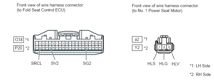
3.CHECK HARNESS AND CONNECTOR (FOLD SEAT CONTROL ECU - NO. 1 POWER SEAT MOTOR)
a.

Disconnect the O34 or P20 ECU connector.
B443216E01
0.458,1.24 0.792,1.438 0.333,0.198 0.458,1.531 0.792,1.729 0.333,0.198 4.427,1.229 4.76,1.427 0.333,0.198 4.427,1.51 4.76,1.708 0.333,0.198 5.844,2.01 5.677,1.615 true 5.49,2.021 5.49,1.635 true 5.135,2.031 5.323,1.635 true 1.292,2.021 1.344,1.615 true 1.844,2.021 1.688,1.615 true 2.885,2.031 2.885,1.615 true 0.563,0.083 2.813,0.469 2.25,0.385 10 false Front view of wire harness connector: (to Fold Seat Control ECU) 4.417,0.104 6.667,0.49 2.25,0.385 10 false Front view of wire harness connector: (to No. 1 Power Seat Motor) 0.5,1.25 0.792,1.438 0.292,0.188 10 false O34 0.5,1.531 0.792,1.719 0.292,0.188 10 false P20 0.854,1.542 1.042,1.75 0.188,0.208 10 false *2 0.844,1.26 1.031,1.469 0.188,0.208 10 false *1 6.354,2.427 7.104,2.635 0.75,0.208 10 false *2: RH Side 6.354,2.135 7.104,2.344 0.75,0.208 10 false *1: LH Side 5.75,2.073 6.063,2.24 0.313,0.167 10 false HLV 5.333,2.063 5.646,2.229 0.313,0.167 10 false HLG 4.938,2.063 5.25,2.229 0.313,0.167 10 false HLS 1.042,2.052 1.427,2.219 0.385,0.167 10 false SRCL 1.708,2.052 2,2.219 0.292,0.167 10 false SV2 2.781,2.052 3.104,2.219 0.323,0.167 10 false SG2 4.51,1.24 4.708,1.427 0.198,0.188 10 false a2 4.51,1.521 4.708,1.708 0.198,0.188 10 false Y2 4.813,1.229 5,1.438 0.188,0.208 10 false *1 4.823,1.542 5.01,1.75 0.188,0.208 10 false *2


b.

Disconnect the a2 or Y2 motor connector.


c.

Measure the resistance according to the value(s) in the table below.

Standard Resistance:
LH Side
Tester Connection Condition Specified Condition
O34-22 (SRCL) - a2-1 (HLS) Always Below 1 Ω
O34-22 (SRCL) - Body ground Always 10 kΩ or higher
O34-25 (SV2) - a2-3 (HLV) Always Below 1 Ω
O34-25 (SV2) - Body ground Always 10 kΩ or higher
O34-36 (SG2) - a2-2 (HLG) Always Below 1 Ω
O34-36 (SG2) - Body ground Always 10 kΩ or higher

LH Side
Tester Connection Condition Specified Condition
P20-22 (SRCL) - Y2-1 (HLS) Always Below 1 Ω
P20-22 (SRCL) - Body ground Always 10 kΩ or higher
P20-25 (SV2) - Y2-3 (HLV) Always Below 1 Ω
P20-25 (SV2) - Body ground Always 10 kΩ or higher
P20-36 (SG2) - Y2-2 (HLG) Always Below 1 Ω
P20-36 (SG2) - Body ground Always 10 kΩ or higher


OK

NG

REPAIR OR REPLACE HARNESS OR CONNECTOR