Home › Vehicle Interior › HEATING / AIR CONDITIONING › AIR CONDITIONING SYSTEM
RM27L0U _58 Vehicle Interior _049344 HEATING / AIR CONDITIONING _0235901 AIR CONDITIONING SYSTEM J

HEATING / AIR CONDITIONING  AIR CONDITIONING SYSTEM  Rear Air Conditioning Control Panel Circuit  


DESCRIPTION

This circuit consists of the air conditioning control and the air conditioning amplifier. When the air conditioning control is operated, signals are transmitted to the air conditioning amplifier through the LIN communication system

If the LIN communication system malfunctions, the air conditioning amplifier does not operate even if the air conditioning control is operated.

WIRING DIAGRAM
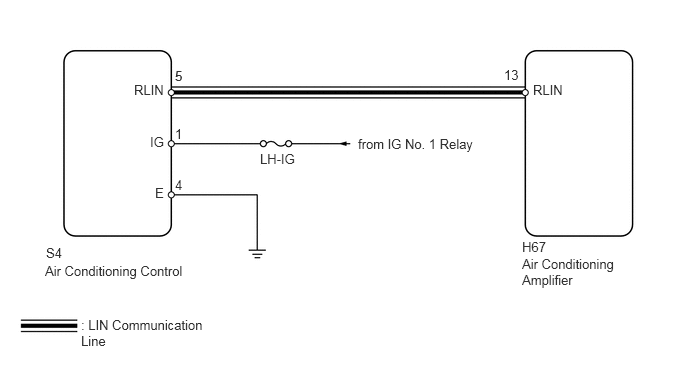
E157369E58
1.396,0.854 1.781,1.021 0.385,0.167 10 false RLIN 1.563,1.396 1.813,1.594 0.25,0.198 10 false IG 1.615,1.927 1.844,2.188 0.229,0.26 10 false E 1.823,0.708 1.948,0.865 0.125,0.156 10 false 5 1.823,1.844 1.948,2 0.125,0.156 10 false 4 1.823,1.313 1.948,1.469 0.125,0.156 10 false 1 5.25,0.698 5.469,0.896 0.219,0.198 10 false 13 5.552,0.854 5.958,1.01 0.406,0.156 10 false RLIN 1.823,0.708 1.948,0.865 0.125,0.156 10 false 5 5.438,2.49 5.74,2.667 0.302,0.177 10 false H67 2.708,1.573 3.271,1.781 0.563,0.208 10 false LH-IG 3.729,1.417 5.031,1.573 1.302,0.156 10 false from IG No. 1 Relay 5.438,2.667 6.5,3.135 1.063,0.469 10 false Air Conditioning Amplifier 0.479,2.552 0.833,2.75 0.354,0.198 10 false S4 0.844,3.302 2.365,3.5 1.521,0.198 10 false : LIN Communication Line 0.469,2.74 4.135,2.938 3.667,0.198 10 false Air Conditioning Control

PROCEDURE

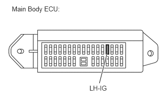
1.INSPECT FUSE (LH-IG)
a.
E345214E01
2.083,1.75 2.24,1.135 true 0.25,0.104 2.396,0.302 2.146,0.198 10 false Main Body ECU: 1.875,1.771 2.646,1.969 0.771,0.198 10 false LH-IG

Remove the LH-IG fuse from the main body ECU.


b.

Measure the resistance according to the value(s) in the table below.

Standard Resistance:
Tester Connection Condition Specified Condition
LH-IG fuse Always Below 1 Ω


OK

2.CHECK HARNESS AND CONNECTOR (AIR CONDITIONING CONTROL - FUSE, BODY GROUND)

NG

REPLACE FUSE

2.CHECK HARNESS AND CONNECTOR (AIR CONDITIONING CONTROL - FUSE, BODY GROUND)
a.

Disconnect the S4 air conditioning control connector.
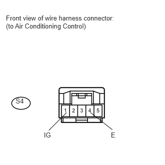

b.
U154058E01
0.124,0.292 2.493,0.661 2.369,0.370 10 Front view of wire harness connector: (to Air Conditioning Control) 2.311,2.727 2.444,2.883 0.133,0.156 10 E 0.914,2.727 1.098,2.897 0.184,0.170 10 IG 1.384,2.348 1.017,2.715 false 1.885,2.345 2.341,2.703 false 0.328,2.024 0.543,2.178 0.215,0.153 10 S4

Measure the resistance and voltage according to the value(s) in the table below.

Standard Resistance:
Tester Connection Condition Specified Condition
S4-4 (E) - Body ground Always Below 1 Ω


Standard Voltage:
Tester Connection Switch Condition Specified Condition
S4-1 (IG) - Body ground Ignition switch ON 11 to 14 V


c.

Reconnect the air conditioning control connector.


OK

3.CHECK HARNESS AND CONNECTOR (AIR CONDITIONING CONTROL - AIR CONDITIONING AMPLIFIER)

NG

REPAIR OR REPLACE HARNESS OR CONNECTOR

3.CHECK HARNESS AND CONNECTOR (AIR CONDITIONING CONTROL - AIR CONDITIONING AMPLIFIER)
a.

Disconnect the S4 air conditioning control connector.
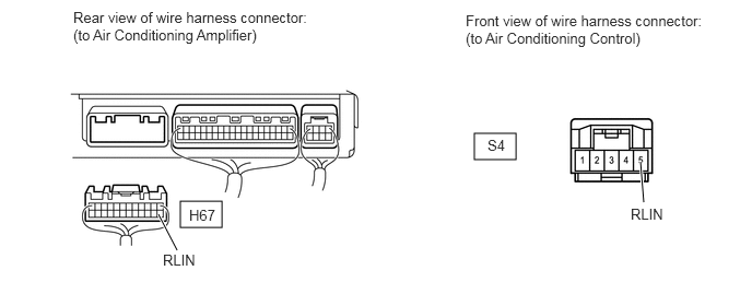
E345215E01
1.719,1.917 2.115,2.167 0.396,0.25 4.521,1.271 4.917,1.521 0.396,0.25 1.688,2.385 1.51,2.042 true 6.135,1.927 6.104,1.542 true 0.698,0.083 2.917,0.625 2.219,0.542 10 false Rear view of wire harness connector: (to Air Conditioning Amplifier) 4.438,0.115 6.729,0.656 2.292,0.542 10 false Front view of wire harness connector: (to Air Conditioning Control) 1.802,1.969 2.26,2.167 0.458,0.198 10 false H67 1.552,2.396 2.167,2.594 0.615,0.198 10 false RLIN 4.646,1.302 4.958,1.5 0.313,0.198 10 false S4 6.01,1.958 6.625,2.156 0.615,0.198 10 false RLIN


b.

Disconnect the H67 air conditioning amplifier connector.


c.

Measure the resistance and voltage according to the value(s) in the table below.

Standard Resistance:
Tester Connection Condition Specified Condition
H67-13 (RLIN) - S4-5 (RLIN) Always Below 1 Ω
S4-5 (RLIN) - Body ground Always 10 kΩ or higher


d.

Reconnect the air conditioning amplifier connector.


e.

Reconnect the air conditioning control connector.


OK

4.REPLACE AIR CONDITIONING CONTROL

NG

REPAIR OR REPLACE HARNESS OR CONNECTOR

4.REPLACE AIR CONDITIONING CONTROL
a.

Replace the air conditioning control with a new or properly functioning one (See pageVehicle Interior>HEATING / AIR CONDITIONING>AIR CONDITIONING PANEL>REMOVAL ).


b.

Operate the rear power seat module to check that it functions properly.

OK:

Rear air conditioning control panel function operates normally.


OK

END

NG