Home › Vehicle Interior › HEATING / AIR CONDITIONING › AIR CONDITIONING SYSTEM
RM27L0U _58 Vehicle Interior _049344 HEATING / AIR CONDITIONING _0235901 AIR CONDITIONING SYSTEM J

HEATING / AIR CONDITIONING  AIR CONDITIONING SYSTEM  Air Conditioning Control Panel does not Operate  


DESCRIPTION

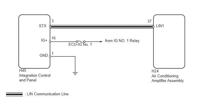
This circuit consists of the integration control and panel and the air conditioning amplifier. When the integration control and panel is operated, signals are transmitted to the air conditioning amplifier through the LIN communication system.

If the LIN communication system malfunctions, the air conditioning amplifier does not operate even if the integration control and panel is operated.

WIRING DIAGRAM
E157369E48
5.564,0.845 5.874,1.026 0.310,0.181 10 LIN1 1.389,0.845 1.741,1.026 0.353,0.181 10 STX 1.463,1.364 1.708,1.545 0.245,0.181 10 IG+ 1.407,1.911 1.732,2.092 0.326,0.181 10 GND 3.744,1.376 5.128,1.550 1.383,0.174 10 from IG NO. 1 Relay 2.444,1.515 3.340,1.696 0.895,0.181 10 ECU-IG No. 1 5.405,2.648 6.802,3.150 1.397,0.502 10 Air Conditioning Amplifier Assembly 5.405,2.47 5.734,2.639 0.328,0.169 10 H24 0.684,2.62 1.844,3.002 1.160,0.382 10 Integration Control and Panel 0.886,3.296 2.501,3.477 1.615,0.181 10 : LIN Communication Line 5.255,0.676 5.426,0.857 0.171,0.181 10 37 1.833,0.667 1.989,0.848 0.156,0.181 10 3 1.833,1.277 2.099,1.459 0.266,0.181 10 16 1.833,1.83 1.989,2.011 0.156,0.181 10 1 0.684,2.446 1.182,2.630 0.498,0.184 10 H45

PROCEDURE

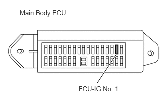
1.INSPECT FUSE (ECU-IG NO. 1)
a.
E345206E01
2.042,1.74 2.438,1.146 true 1.646,1.781 2.521,1.969 0.875,0.188 10 false ECU-IG No. 1 0.417,0.188 2.563,0.385 2.146,0.198 10 false Main Body ECU:

Remove the ECU-IG No. 1 fuse from the main body ECU.


b.

Measure the resistance according to the value(s) in the table below.

Standard Resistance:
Tester Connection Condition Specified Condition
ECU-IG No. 1 fuse Always Below 1 Ω


OK

2.CHECK HARNESS AND CONNECTOR (INTEGRATION CONTROL AND PANEL - BATTERY, BODY GROUND)

NG

REPAIR FUSE

2.CHECK HARNESS AND CONNECTOR (INTEGRATION CONTROL AND PANEL - BATTERY, BODY GROUND)
a.
U154055E01
0.1,0.211 2.516,0.601 2.415,0.390 10 Front view of wire harness connector: (to Integration Control and Panel) 0.237,2.024 0.537,2.165 0.299,0.142 10 H45 0.245,2.74 0.600,2.903 0.355,0.163 10 GND 2.649,2.74 2.955,2.900 0.306,0.161 10 IG+ 0.664,2.808 1.198,2.213 false 2.226,2.442 2.599,2.815 false

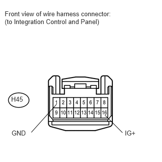
Disconnect the H45 integration control and panel connector.

b.

Measure the resistance and voltage according to the value(s) in the table below.

Standard Resistance:
Tester Connection Condition Specified Condition
H45-1 (GND) - Body ground Always Below 1 Ω


Standard Voltage:
Tester Connection Switch Condition Specified Condition
H45-1 (GND) - H45-16 (IG+) Ignition switch ON 11 to 14 V


c.

Reconnect the integration control and panel connector.


OK

3.CHECK HARNESS AND CONNECTOR (AIR CONDITIONING AMPLIFIER - INTEGRATION CONTROL AND PANEL)

NG

REPAIR OR REPLACE HARNESS OR CONNECTOR

3.CHECK HARNESS AND CONNECTOR (AIR CONDITIONING AMPLIFIER - INTEGRATION CONTROL AND PANEL)
a.

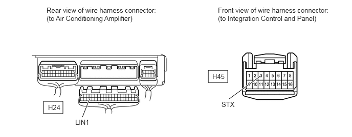
Disconnect the H45 integration control and panel connector.

E345209E01
0.885,2.073 1.281,2.323 0.396,0.25 4.24,1.438 4.635,1.688 0.396,0.25 1.677,2.396 1.823,2.021 true 4.667,2.021 5.292,1.563 true 0.948,0.125 3.219,0.75 2.271,0.625 10 false Rear view of wire harness connector: (to Air Conditioning Amplifier) 4.438,0.125 6.708,0.75 2.271,0.625 10 false Front view of wire harness connector: (to Integration Control and Panel) 0.979,2.115 1.438,2.313 0.458,0.198 10 false H24 4.323,1.479 4.781,1.677 0.458,0.198 10 false H45 1.531,2.417 2.146,2.615 0.615,0.198 10 false LIN1 4.51,2.052 4.969,2.25 0.458,0.198 10 false STX


b.

Disconnect the H24 air conditioning amplifier connector.


c.

Measure the resistance according to the value(s) in the table below.

Standard Resistance:
Tester Connection Condition Specified Condition
H45-3 (STX) - H24-37 (LIN1) Always Below 1 Ω
H45-3 (STX) - Body ground Always 10 kΩ or higher


d.

Reconnect the air conditioning amplifier connector.


e.

Reconnect the integration control and panel connector.


OK

4.REPLACE INTEGRATION CONTROL AND PANEL

NG

REPAIR OR REPLACE HARNESS OR CONNECTOR

4.REPLACE INTEGRATION CONTROL AND PANEL
a.

Replace the integration control and panel with a new or properly functioning one (See page Vehicle Interior>HEATING / AIR CONDITIONING>AIR CONDITIONING PANEL>REMOVAL).


b.

Operate the air conditioning control to check that it functions properly.

OK:

Air conditioning control function operates normally.


OK

END (INTEGRATION CONTROL AND PANEL IS FAULTY)

NG