HEATING / AIR CONDITIONING FRONT AIR CONDITIONING UNIT REASSEMBLY
PROCEDURE

 88515
1.INSTALL COOLER EXPANSION VALVE
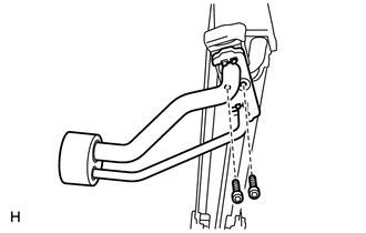
Sufficiently apply compressor oil to 4 new O-rings and the fitting surface of the hose joint.
- Compressor oil:
ND-OIL 8 or equivalent
Install the 2 O-rings to the cooler evaporator.
Install the 2 O-rings to the tube and accessory.
Install the cooler expansion valve and the tube and accessory to the evaporator.
Using a 4 mm hexagon wrench, install the 2 bolts.
- Torque:
- 3.5 N*m (36 kgf*cm, 31 in.*lbf)
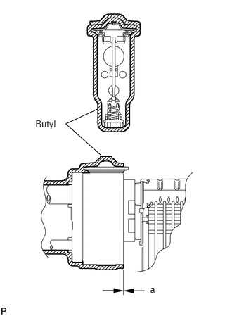
Install a new butyl, as shown in the illustration.
- Standard:
Item Specified Condicion a -5 mm (-0.197 in.) to 0 mm (0 in.)
88625
2.INSTALL EVAPORATOR TEMPERATURE SENSOR
88501
3.INSTALL NO. 1 COOLER EVAPORATOR SUB-ASSEMBLY
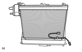
Install the evaporator to the blower case.
- HINT:
-
If a new cooler evaporator is installed, add compressor oil to the cooler evaporator as follows.
- Compressor oil:
ND-OIL 8 or equivalent. Add 40 cc (1.35 fl. oz.)
87107A
4.INSTALL HEATER RADIATOR UNIT SUB-ASSEMBLY
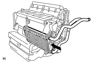
Install the heater radiator unit.
87050
5.INSTALL AIR CONDITIONING RADIATOR ASSEMBLY
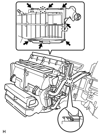
Attach the 3 claws and install the air conditioning radiator.
Install the 6 screws.
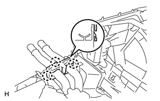
Attach the 3 claws and install the heater clamp.
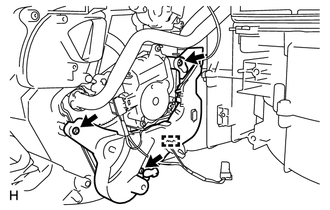
Install the plate with the 3 screws.
Attach the clamp.
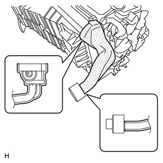
Install a new packing, as shown in the illustration.
87106B
6.INSTALL COOLING UNIT DAMPER SERVO SUB-ASSEMBLY
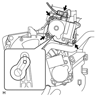
Install the damper servo with the 3 screws, as shown in the illustration.
Connect the connector.
87106G
7.INSTALL BLOWER DAMPER SERVO SUB-ASSEMBLY
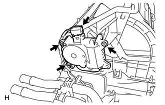
Install the damper servo with the 3 screws.
Connect the connector.
87106L
8.INSTALL DAMPER SERVO SUB-ASSEMBLY
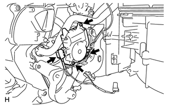
Install the damper servo with the 3 screws.
Connect the connector.
87106D
9.INSTALL DAMPER SERVO SUB-ASSEMBLY
Set the damper servo so that the cutout part engages with the tooth of the gear, and attach the claw to install the damper servo.
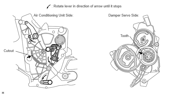
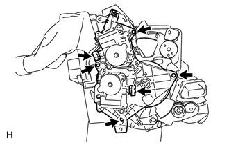
Install the 4 screws and connect the 2 connectors.
10.INSTALL AIR DUCT
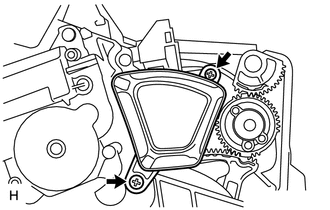
Install the duct with the 2 screws.
87103B
11.INSTALL BLOWER WITH FAN MOTOR SUB-ASSEMBLY
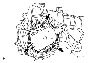
Install the motor with the 3 screws.
88650E
12.INSTALL AIR CONDITIONING AMPLIFIER ASSEMBLY
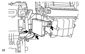
Install the amplifier with the 2 screws.
Connect the connector.
87201B
13.INSTALL NO. 2 AIR DUCT SUB-ASSEMBLY
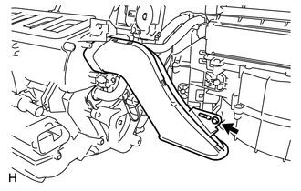
Install the air duct with the screw.
88669B
14.INSTALL COOLER AIR HOSE
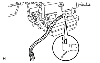
Attach the 2 claws and install the cooler air hose.
89780
15.INSTALL TRANSPONDER KEY ECU ASSEMBLY
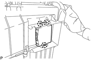
Attach the 3 claws and install the transponder key ECU.
87139D
16.INSTALL AIR REFINER ELEMENT
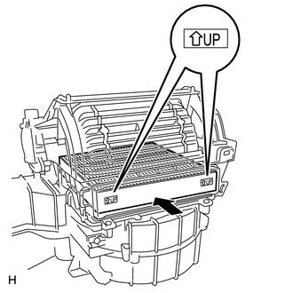
Install the air refiner element into the blower case.
- NOTICE:
-
Install the air refiner element with its UP marks oriented in the correct direction.
88899M
17.INSTALL AIR FILTER COVER PLATE
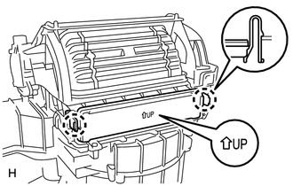
Attach the 2 clips and install the air filter cover plate.
- NOTICE:
-
Install the air filter cover plate with its UP mark oriented in the correct direction.
87201F
18.INSTALL NO. 3 AIR DUCT SUB-ASSEMBLY
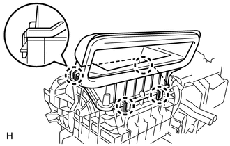
Attach the 4 claws and install the air duct.
55990B
19.INSTALL LOWER DEFROSTER NOZZLE ASSEMBLY
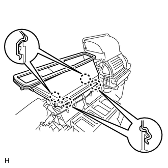
Attach the 4 claws and install the nozzle.