Home › Vehicle Exterior › SLIDING ROOF / CONVERTIBLE › SLIDING ROOF SYSTEM
RM27L0U _59 Vehicle Exterior _049348 SLIDING ROOF / CONVERTIBLE _0235952 SLIDING ROOF SYSTEM J

SLIDING ROOF / CONVERTIBLE  SLIDING ROOF SYSTEM  Sliding Roof ECU Power Source Circuit  


DESCRIPTION

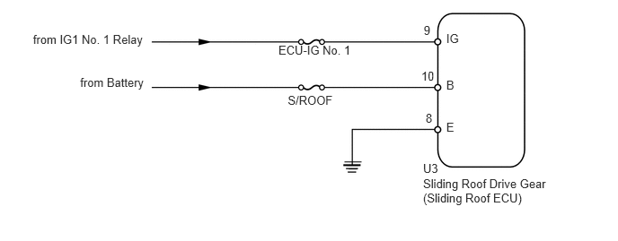
If the sliding function and tilt function do not operate, there may be a malfunction in the sliding roof ECU power source circuit.

WIRING DIAGRAM
B171240E04
4.906,1.874 5.120,2.031 0.215,0.157 10 U3 5.175,1.392 5.383,1.602 0.208,0.210 10 E 5.175,0.369 5.439,0.579 0.263,0.210 10 IG 4.913,0.271 5.079,0.481 0.166,0.210 10 9 4.885,0.804 5.079,1.013 0.194,0.210 10 10 4.936,1.294 5.130,1.504 0.194,0.210 10 8 5.175,0.902 5.439,1.112 0.263,0.210 10 B 0.383,0.374 1.822,0.572 1.439,0.199 10 from IG1 No. 1 Relay 0.929,0.878 1.771,1.077 0.842,0.199 10 from Battery 3.337,1.083 3.957,1.282 0.620,0.199 10 S/ROOF 3.994,1.882 4.193,1.882 false 4.024,1.923 4.162,1.923 false 4.044,1.964 4.141,1.964 false 3.229,0.505 4.170,0.668 0.941,0.163 10 ECU-IG No. 1 4.906,2.049 6.446,2.396 1.541,0.347 10 Sliding Roof Drive Gear (Sliding Roof ECU)

PROCEDURE

1.READ VALUE USING TECHSTREAM (IGNITION SWITCH SIGNAL)
a.

Connect the Techstream to the DLC3.


b.

Turn the ignition switch to ON.


c.

Turn the Techstream ON.


d.

Enter the following menus: Body Electrical / Sliding Roof / Data List.


e.

According to the display on the Techstream, read the Data List.

Sliding Roof
Tester Display Test Part Control Range Diagnostic Note
Ignition (Direct Signal) Ignition switch signal/ON or OFF ON: Ignition switch ON
OFF: Ignition switch off
-
Ignition (MPX) Ignition switch signal (MPX signal)/ON or OFF ON: Ignition switch ON
OFF: Ignition switch off
-

OK:

The Techstream displays as shown in the table according to the operation of each switch.


OK

REPLACE SLIDING ROOF DRIVE GEAR SUB-ASSEMBLY (SLIDING ROOF ECU)

NG

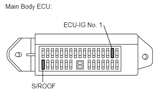
2.INSPECT FUSE (S/ROOF, ECU-IG No. 1)
a.
B443497E01
0.917,1.479 0.917,1.76 false 2.406,1.042 2.229,0.542 false 0.115,0.052 2.26,0.25 2.146,0.198 10 false Main Body ECU: 0.677,1.76 1.208,1.969 0.531,0.208 10 false S/ROOF 1.365,0.448 3.198,0.646 1.833,0.198 10 false ECU-IG No. 1

Remove the S/ROOF and ECU-IG No. 1 fuses from the main body ECU.


b.

Measure the resistance according to the value(s) in the table below.

Standard Resistance:
Tester Connection Condition Specified Condition
S/ROOF fuse Always Below 1 Ω
ECU-IG No. 1 fuse Always Below 1 Ω


OK

3.CHECK HARNESS AND CONNECTOR (SLIDING ROOF ECU - BATTERY AND BODY GROUND)

NG

CHECK FOR SHORTS IN ALL HARNESSES AND CONNECTORS CONNECTED TO FUSE AND REPLACE FUSE

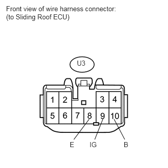
3.CHECK HARNESS AND CONNECTOR (SLIDING ROOF ECU - BATTERY AND BODY GROUND)
a.
U153157E02
2.104,2.438 1.938,2.854 false 1.823,2.438 1.51,2.854 false 2.333,2.438 2.552,2.854 false 0.125,0.094 2.396,0.438 2.271,0.344 10 false Front view of wire harness connector: (to Sliding Roof ECU) 1.573,1.208 1.771,1.354 0.198,0.146 10 false U3 1.833,2.875 2.021,3.042 0.188,0.167 10 false IG 1.427,2.875 1.615,3.042 0.188,0.167 10 false E 2.531,2.875 2.781,3.042 0.25,0.167 10 false B

Disconnect the U3 ECU connector.


b.

Measure the voltage according to the value(s) in the table below.

Standard Voltage :
Tester Connection Switch Condition Specified Condition
U3-9 (IG) - Body ground Ignition switch ON 11 to 14 V
Ignition switch off Below 1 V
U3-10 (B) - Body ground Always 11 to 14 V


c.

Measure the resistance according to the value(s) in the table below.

Standard Resistance:
Tester Connection Condition Specified Condition
U3-8 (E) - Body ground Always Below 1 Ω


OK

REPLACE SLIDING ROOF DRIVE GEAR SUB-ASSEMBLY (SLIDING ROOF ECU)

NG

REPAIR OR REPLACE HARNESS OR CONNECTOR