Home › Vehicle Exterior › DOOR / HATCH › BACK DOOR CLOSER SYSTEM
RM27L0U _59 Vehicle Exterior _049349 DOOR / HATCH _0235967 BACK DOOR CLOSER SYSTEM J

DOOR / HATCH  BACK DOOR CLOSER SYSTEM  Back Door cannot be Opened  


DESCRIPTION

When the back door cannot be opened, one of the following may be the cause: 1) power back door ECU malfunction, 2) back door lock malfunction, 3) back door open switch malfunction, 4) main body ECU malfunction, 5) back door ECU malfunction, 6) power source circuit malfunction, or 7) position SW in prohibit condition. In the case that a fault is detected at the position switch, the back door stops functioning when the door position is full-latch (system prohibits opening of the door). Thereafter, the system prohibits back door operation until it detects a power reset of the ECU.

HINT:

Since the power back door system has functions that use CAN and LIN communication, first confirm that there is no malfunction in the communication system by inspecting the CAN and LIN communication functions in accordance with the "How to Proceed with Troubleshooting" procedures. Then, conduct the following inspection procedure.


WIRING DIAGRAM
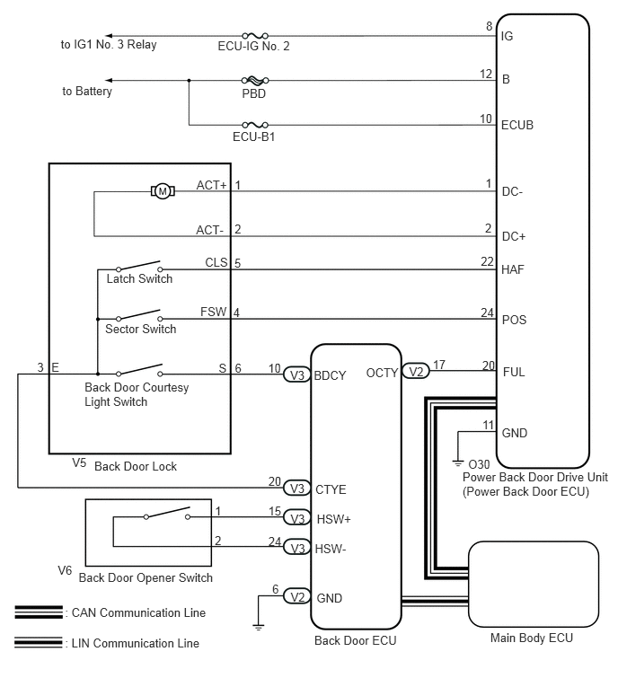
U153294E01
5.82,2.134 6.115,2.283 0.295,0.149 10 DC- 5.821,2.657 6.138,2.799 0.317,0.143 10 DC+ 5.813,3.047 6.109,3.200 0.296,0.153 10 HAF 5.821,3.627 6.154,3.785 0.333,0.158 10 POS 5.833,4.234 6.130,4.380 0.296,0.147 10 FUL 5.817,4.935 6.182,5.079 0.365,0.144 10 GND 5.592,4.845 5.766,4.996 0.174,0.152 10 11 5.592,4.152 5.765,4.291 0.173,0.139 10 20 5.576,3.539 5.773,3.692 0.197,0.153 10 24 5.576,2.953 5.767,3.114 0.191,0.161 10 22 5.625,2.567 5.739,2.718 0.114,0.151 10 2 5.629,2.044 5.739,2.203 0.110,0.159 10 1 2.279,2.06 2.668,2.207 0.390,0.147 10 ACT+ 2.275,2.582 2.665,2.729 0.390,0.147 10 ACT- 2.721,2.576 2.835,2.718 0.114,0.143 10 2 2.72,2.058 2.826,2.201 0.106,0.143 10 1 2.377,2.959 2.665,3.106 0.288,0.147 10 CLS 2.324,3.535 2.677,3.686 0.353,0.151 10 FSW 2.536,4.189 2.667,4.335 0.130,0.147 10 S 2.718,2.966 2.832,3.108 0.114,0.143 10 5 0.431,4.174 0.545,4.317 0.114,0.143 10 3 2.724,4.184 2.830,4.335 0.106,0.151 10 6 0.596,4.176 0.714,4.323 0.118,0.148 10 E 2.704,3.538 2.806,3.693 0.102,0.155 10 4 2.491,5.839 2.597,6.002 0.106,0.163 10 1 2.491,6.192 2.597,6.333 0.106,0.142 10 2 3.108,4.186 3.305,4.346 0.196,0.160 10 10 3.365,4.273 3.566,4.411 0.201,0.137 10 V3 3.639,4.271 4.051,4.427 0.412,0.155 10 BDCY 4.244,4.237 4.658,4.388 0.414,0.151 10 OCTY 4.745,4.226 4.950,4.374 0.204,0.149 10 V2 5.017,4.143 5.198,4.298 0.180,0.155 10 17 3.369,5.934 3.569,6.072 0.201,0.137 10 V3 3.372,6.281 3.573,6.418 0.201,0.137 10 V3 3.365,5.587 3.566,5.725 0.201,0.137 10 V3 3.37,6.847 3.574,6.996 0.204,0.149 10 V2 3.656,5.59 4.054,5.729 0.398,0.140 10 CTYE 3.674,5.94 4.113,6.086 0.439,0.146 10 HSW+ 3.651,6.28 4.090,6.427 0.439,0.146 10 HSW- 3.67,6.858 4.000,7.006 0.330,0.149 10 GND 1.094,5.319 2.123,5.479 1.029,0.160 10 Back Door Lock 0.911,6.618 2.554,6.769 1.642,0.151 10 Back Door Opener Switch 0.754,7.024 2.609,7.166 1.854,0.142 10 : CAN Communication Line 0.754,7.38 2.593,7.522 1.839,0.142 10 : LIN Communication Line 3.645,7.349 4.670,7.493 1.024,0.145 10 Back Door ECU 5.686,7.316 6.723,7.471 1.037,0.155 10 Main Body ECU 5.364,5.453 7.113,5.780 1.749,0.328 10 Power Back Door Drive Unit (Power Back Door ECU) 1.235,3.151 2.064,3.299 0.829,0.148 10 Latch Switch 1.219,3.734 2.100,3.896 0.881,0.162 10 Sector Switch 0.981,4.406 2.271,4.715 1.291,0.309 10 Back Door Courtesy Light Switch 0.705,0.432 1.899,0.610 1.193,0.178 10 to IG1 No. 3 Relay 0.723,0.965 1.368,1.123 0.645,0.159 10 to Battery 2.525,0.45 3.415,0.606 0.890,0.156 10 ECU-IG No. 2 2.806,1.004 3.128,1.158 0.321,0.154 10 PBD 2.698,1.497 3.356,1.658 0.658,0.160 10 ECU-B1 5.807,0.335 6.001,0.490 0.194,0.154 10 IG 5.823,0.835 5.947,1.001 0.124,0.166 10 B 5.811,1.365 6.227,1.537 0.417,0.172 10 ECUB 5.636,0.215 5.749,0.381 0.112,0.166 10 8 5.558,0.766 5.785,0.910 0.227,0.144 10 12 5.558,1.293 5.757,1.438 0.199,0.145 10 10 0.836,5.286 1.026,5.435 0.190,0.149 10 V5 0.67,6.536 0.876,6.688 0.205,0.152 10 V6 5.429,5.302 5.738,5.440 0.308,0.138 10 O30 3.112,5.504 3.295,5.646 0.183,0.142 10 20 3.11,5.845 3.298,5.992 0.188,0.147 10 15 3.112,6.196 3.295,6.343 0.183,0.147 10 24 3.157,6.746 3.252,6.909 0.095,0.162 10 6

PROCEDURE

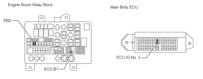
1.INSPECT FUSES (ECU-IG NO. 2, ECU-B1, PBD)
a.

Remove the ECU- IG No. 2, ECU-B1 and PBD fuses.

E344963E01
0.448,0.729 0.635,0.729 0.635,0.729 1.198,1.49 true 2.083,2.448 2.271,2.448 2.271,2.448 2.5,1.885 true 4.99,2.052 5.177,2.052 5.177,2.052 5.521,1.552 true 0.281,0.083 2.156,0.292 1.875,0.208 10 false Engine Room Relay Block: 0.125,0.646 0.635,0.823 0.51,0.177 10 false PBD 1.563,2.365 2.625,2.563 1.063,0.198 10 false ECU-B1 3.896,0.167 5.698,0.385 1.802,0.219 10 false Main Body ECU: 4.115,1.948 5.177,2.146 1.063,0.198 10 false ECU-IG No. 2

b.

Measure the resistance according to the value(s) in the table below.

Standard Resistance:
Tester Connection Condition Specified Condition
ECU-IG No. 2 Always Below 1 Ω
ECU-B1 Always Below 1 Ω
PBD Always Below 1 Ω


c.

Reinstall the fuses.


OK

2.CHECK HARNESS AND CONNECTOR (POWER SOURCE)

NG

CHECK FOR SHORTS IN ALL HARNESSES AND CONNECTORS CONNECTED TO FUSE AND REPLACE FUSE

2.CHECK HARNESS AND CONNECTOR (POWER SOURCE)
a.

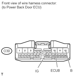
Disconnect the O30 power back door ECU connector.

b.
U153174E02
1.927,2.156 1.552,2.771 true 2.25,2.104 2.344,2.75 true 2.698,2.104 2.875,2.76 true 0.073,0.042 2.448,0.375 2.375,0.333 10 false Front view of wire harness connector: (to Power Back Door ECU) 1.438,2.823 1.677,3 0.24,0.177 10 false IG 2.073,2.802 2.563,2.979 0.49,0.177 10 false ECUB 2.875,2.802 3.021,2.979 0.146,0.177 10 false B 0.146,2 0.458,2.177 0.313,0.177 10 false O30

Measure the voltage according to the value(s) in the table below.

Standard Voltage:
Tester Connection Condition Specified Condition
O30-8 (IG) - Body ground Ignition switch ON 11 to 14 V
O30-10 (ECUB) - Body ground Always 11 to 14 V
O30-12 (B) - Body ground Always 11 to 14 V


c.

Reconnect the power back door ECU connector.


OK

3.CHECK HARNESS AND CONNECTOR (BODY GROUND)

NG

REPAIR OR REPLACE HARNESS OR CONNECTOR

3.CHECK HARNESS AND CONNECTOR (BODY GROUND)
a.

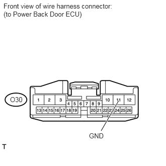
Disconnect the O30 power back door ECU connector.

b.
U153175E02
2.458,2.083 2.094,2.708 true 0.073,0.042 2.448,0.375 2.375,0.333 10 false Front view of wire harness connector: (to Power Back Door ECU) 1.844,2.729 2.24,2.906 0.396,0.177 10 false GND 0.208,1.979 0.521,2.156 0.313,0.177 10 false O30

Measure the resistance according to the value(s) in the table below.

Standard Resistance:
Tester Connection Condition Specified Condition
O30-11 (GND) - Body ground Always Below 1 Ω


c.

Reconnect the power back door ECU connector.


OK

4.READ VALUE USING TECHSTREAM

NG

REPAIR OR REPLACE HARNESS OR CONNECTOR

4.READ VALUE USING TECHSTREAM
a.

Connect the Techstream to the DLC3.


b.

Turn the ignition switch to ON.


c.

Turn the Techstream on.


d.

Enter the following menus: Body Electrical / Back Door P/W / Data List /


e.

According to the display on the Techstream, read the Data List.

Back Door P/W (Back Door ECU)
Tester Display Measurement Item/Range Normal Condition Diagnostic Note
Back Door Open Handle SW Back door opener switch / ON or OFF ON: Back door opener switch is pushed
OFF: Back door opener switch is not pushed
-

OK:

The back door opener switch functions as specified in the normal condition.


OK

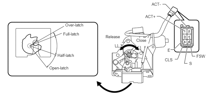
5.INSPECT BACK DOOR LOCK

NG

7.INSPECT BACK DOOR OPENER SWITCH
5.INSPECT BACK DOOR LOCK
B191744E13
6.76,1.948 6.656,1.948 6.656,1.948 6.552,1.271 true 5.906,1.719 6.01,1.719 6.01,1.719 6.417,1.323 true 6.49,2.198 6.385,2.198 6.385,2.198 6.51,1.479 true 6.052,2.052 6.146,2.052 6.146,2.052 6.385,1.448 true 5.427,0.563 5.531,0.563 5.531,0.563 6.375,1.063 true 5.625,0.146 5.729,0.146 5.729,0.146 6.542,1 true 6.802,1.865 7.156,2.021 0.354,0.156 10 false FSW 5.802,1.656 5.927,1.802 0.125,0.146 10 false E 4.719,1.313 5.146,1.594 0.427,0.281 10 true Close 3.656,1.188 4.219,1.531 0.563,0.344 10 true Release 2.26,0.781 2.927,0.927 0.667,0.146 10 false Over-latch 2.188,1.094 2.781,1.25 0.594,0.156 10 false Full-latch 1.99,1.833 2.615,1.979 0.625,0.146 10 false Half-latch 1.708,2.271 2.438,2.438 0.729,0.167 10 false Open-latch 6.552,2.115 6.698,2.271 0.146,0.156 10 false S 5.708,1.99 6.052,2.135 0.344,0.146 10 false CLS 5.031,0.49 5.427,0.635 0.396,0.146 10 false ACT+ 5.25,0.063 5.625,0.229 0.375,0.167 10 false ACT-

a.

Remove the back door lock (See page Vehicle Interior>DOOR LOCK>BACK DOOR LOCK>REMOVAL).


b.

Apply battery voltage and check operation of the door lock motor.

Apply Battery Voltage:
Measurement Condition Specified Condition
Battery positive (+) → Terminal 2 (ACT-)
Battery negative (-) → Terminal 1 (ACT+)
Latch turns to open-latch position
Battery positive (+) → Terminal 1 (ACT+)
Battery negative (-) → Terminal 2 (ACT-)
Latch turns to full-latch position


c.

Measure the resistance according to the value(s) in the table below.

Standard Resistance:

Latch Switch

Tester Connection Door Lock Latch Position Specified Condition
5 (CLS) - 3 (E) Over-latch Below 1 Ω
5 (CLS) - 3 (E) Open-latch 10 kΩ or higher
5 (CLS) - 3 (E) Full-latch 10 kΩ or higher
5 (CLS) - 3 (E) Half-latch 10 kΩ or higher


Standard Resistance:

Sector Switch

Tester Connection Door Lock Latch Position Specified Condition
4 (FSW) - 3 (E) Open-latch Below 1 Ω
4 (FSW) - 3 (E) Over-latch 10 kΩ or higher
4 (FSW) - 3 (E) Full-latch 10 kΩ or higher
4 (FSW) - 3 (E) Half-latch 10 kΩ or higher


Standard Resistance:

Back Door Courtesy Light Switch

Tester Connection Door Lock Latch Position Specified Condition
6 (S) - 3 (E) Open-latch Below 1 Ω
6 (S) - 3 (E) Half-latch Below 1 Ω
6 (S) - 3 (E) Full-latch 10 kΩ or higher
6 (S) - 3 (E) Over-latch 10 kΩ or higher


OK

6.CHECK HARNESS AND CONNECTOR (BACK DOOR LOCK - POWER BACK DOOR ECU, BACK DOOR ECU)

NG

REPLACE BACK DOOR LOCK

6.CHECK HARNESS AND CONNECTOR (BACK DOOR LOCK - POWER BACK DOOR ECU, BACK DOOR ECU)
a.

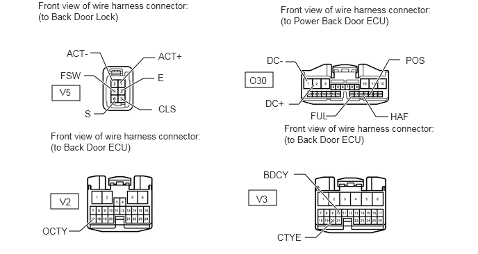
Disconnect the V5 back door lock connector.
B443244E03
0.781,1.281 1.198,1.51 0.417,0.229 3.677,1.083 4.094,1.313 0.417,0.229 0.76,2.906 1.177,3.135 0.417,0.229 3.729,2.854 4.146,3.083 0.417,0.229 1.802,1.24 2.156,0.865 2.156,0.865 2.323,0.865 true 5.438,1.427 5.635,1.75 5.635,1.75 5.823,1.75 true 1.385,3.302 1.198,3.469 1.198,3.469 1.031,3.469 true 4.573,3.563 4.74,3.563 4.74,3.563 4.99,3.313 true 1.833,1.354 2.146,1.177 2.146,1.177 2.313,1.177 true 1.833,1.49 2.094,1.646 2.094,1.646 2.281,1.646 true 1.729,1.51 1.552,1.708 1.552,1.708 1.406,1.708 true 1.688,1.219 1.5,0.792 1.5,0.792 1.354,0.792 true 4.604,1.219 4.427,0.927 4.427,0.927 4.281,0.927 true 4.708,1.271 4.479,1.563 4.479,1.563 4.333,1.563 true 5.271,1.448 5.031,1.74 5.031,1.74 4.885,1.74 true 4.406,2.615 4.573,2.615 4.573,2.615 5.083,3.177 true 1.719,1.375 1.406,1.135 1.406,1.135 1.26,1.135 true 5.552,1.406 5.833,0.896 5.833,0.896 6,0.896 true 0.573,0 2.865,0.344 2.292,0.344 10 false Front view of wire harness connector: (to Back Door Lock) 4.208,0.063 6.448,0.417 2.24,0.354 10 false Front view of wire harness connector: (to Power Back Door ECU) 0.76,1.958 3.042,2.302 2.281,0.344 10 false Front view of wire harness connector: (to Back Door ECU) 4.26,1.844 6.542,2.188 2.281,0.344 10 false Front view of wire harness connector: (to Back Door ECU) 0.896,1.302 1.146,1.469 0.25,0.167 10 false V5 2.375,0.76 2.885,0.938 0.51,0.177 10 false ACT+ 2.375,1.552 2.823,1.771 0.448,0.219 10 false CLS 5.854,1.667 6.302,1.885 0.448,0.219 10 false HAF 3.74,1.125 4.198,1.344 0.458,0.219 10 false O30 0.896,2.948 1.146,3.115 0.25,0.167 10 false V2 0.635,3.385 1.083,3.604 0.448,0.219 10 false OCTY 3.844,2.906 4.094,3.073 0.25,0.167 10 false V3 4.156,3.479 4.604,3.698 0.448,0.219 10 false CTYE 2.365,1.083 2.875,1.26 0.51,0.177 10 false E 1.271,1.625 1.563,1.844 0.292,0.219 10 false S 1,0.719 1.51,0.896 0.51,0.177 10 false ACT- 4.656,1.656 5.104,1.875 0.448,0.219 10 false FUL 4,0.823 4.448,1.042 0.448,0.219 10 false DC- 3.979,1.469 4.427,1.688 0.448,0.219 10 false DC+ 3.948,2.542 4.396,2.76 0.448,0.219 10 false BDCY 0.906,1.052 1.417,1.229 0.51,0.177 10 false FSW 6.083,0.823 6.531,1.042 0.448,0.219 10 false POS


b.

Disconnect the O30, V2 and V3 ECU connector.


c.

Measure the resistance according to the value(s) in the table below.

Standard Resistance:
Tester Connection Condition Specified Condition
V5-1 (ACT+) - O30-1 (DC-) Always Below 1 Ω
V5-2 (ACT-) - O30-2 (DC+) Always Below 1 Ω
V5-5 (CLS) - O30-22 (HAF) Always Below 1 Ω
V5-4 (FSW) - O30-24 (POS) Always Below 1 Ω
V5-6 (S) - V3-10 (BDCY) Always Below 1 Ω
V5-3 (E) - V3-20 (CTYE) Always Below 1 Ω
V2-17 (OCTY) - O30-20 (FUL) Always Below 1 Ω
O30-1 (DC-) - Body ground Always 10 kΩ or higher
O30-2 (DC+) - Body ground Always 10 kΩ or higher
O30-22 (HAF) - Body ground Always 10 kΩ or higher
O30-24 (POS) - Body ground Always 10 kΩ or higher
O30-20 (FUL) - Body ground Always 10 kΩ or higher


d.

Disconnect the back door lock connector.


e.

Disconnect the ECU connector.


Result
Result Proceed to
NG A
OK B


A

REPAIR OR REPLACE HARNESS OR CONNECTOR

B

9.REPLACE BACK DOOR ECU
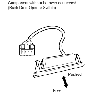
7.INSPECT BACK DOOR OPENER SWITCH
a.
B190834E01
2.34,2.464 2.843,2.609 0.503,0.145 10 Pushed 1.823,3.032 2.137,3.188 0.314,0.156 10 Free 0.275,0.015 2.764,0.336 2.489,0.321 10 Component without harness connected: (Back Door Opener Switch)

Remove the back door opener switch (See page Vehicle Exterior>DOOR / HATCH>BACK DOOR>DISASSEMBLY).


b.

Measure the resistance according to the value(s) in the table below.

Standard Resistance:
Tester Connection Switch Condition Specified Condition
1 - 2 Back door opener switch free 10 kΩ or higher
1 - 2 Back door opener switch pushed Below 1 Ω


OK

8.CHECK HARNESS AND CONNECTOR (BACK DOOR OPENER SWITCH - BACK DOOR ECU)

NG

REPLACE BACK DOOR OPENNER SWITCH

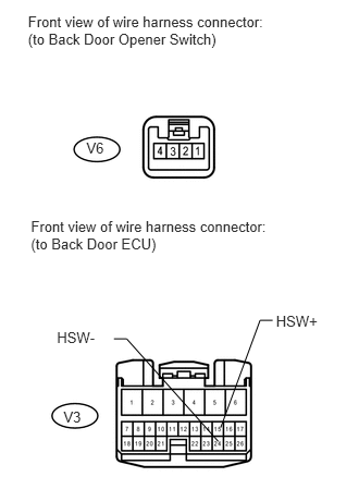
8.CHECK HARNESS AND CONNECTOR (BACK DOOR OPENER SWITCH - BACK DOOR ECU)
a.
U153298E01
0.268,0.129 2.596,0.483 2.328,0.354 10 Front view of wire harness connector: (to Back Door Opener Switch) 0.296,2.085 2.625,2.456 2.328,0.370 10 Front view of wire harness connector: (to Back Door ECU) 0.608,3.908 0.828,4.063 0.221,0.155 10 V3 2.643,2.993 3.082,3.143 0.439,0.150 10 HSW+ 0.545,3.15 0.984,3.300 0.439,0.150 10 HSW- 2.611,3.063 2.49,3.063 2.49,3.063 2.113,4.089 false 1.091,3.24 1.212,3.24 1.212,3.24 2.089,4.221 false 0.827,1.331 1.022,1.483 0.194,0.152 10 V6

Disconnect the V6 switch connector.


b.

Disconnect the V3 ECU connector.


c.

Measure the resistance according to the value(s) in the table below.

Standard Resistance:
Tester Connection Condition Specified Condition
V6-1 - V3-15 (HSW+) Always Below 1 Ω
V6-2 - V3-24 (HSW-) Always Below 1 Ω
V6-1 or V3-15 (HSW+) - Body ground Always 10 kΩ or higher
V6-2 or V3-24 (HSW-) - Body ground Always 10 kΩ or higher


d.

Disconnect the switch and ECU connector.


OK

9.REPLACE BACK DOOR ECU

NG

REPAIR OR REPLACE HARNESS OR CONNECTOR

9.REPLACE BACK DOOR ECU
a.

Temporarily replace the back door ECU with a new or normally functioning one (See page Vehicle Exterior>DOOR / HATCH>BACK DOOR>DISASSEMBLY).


NEXT

10.CHECK BACK DOOR CLOSER SYSTEM (OPERATION)
a.

Check that the back door closer operates normally.

OK:

It operates normally.


OK

END (BACK DOOR ECU DEFECTIVE)

NG

11.REPLACE POWER BACK DOOR UNIT (POWER BACK DOOR ECU)
a.

Temporarily replace the power back door drive unit (power back door ECU) with a new or normally functioning one (See page Vehicle Exterior>DOOR / HATCH>POWER BACK DOOR DRIVE UNIT>REMOVAL).


NEXT

12.CHECK BACK DOOR CLOSER SYSTEM (OPERATION)
a.

Check that the back door closer operates normally.

OK:

It operates normally.


OK

END (POWER BACK DOOR DRIVE UNIT (POWER BACK DOOR ECU) DEFECTIVE)

NG

REPLACE MAIN BODY ECU