Home › Vehicle Exterior › DOOR / HATCH › POWER BACK DOOR SYSTEM
RM27L0U _59 Vehicle Exterior _049349 DOOR / HATCH _0235968 POWER BACK DOOR SYSTEM J

DOOR / HATCH  POWER BACK DOOR SYSTEM  Power Back Door Warning System does not Operate  


DESCRIPTION

When the power back door warning system does not operate, one of the following may be malfunctioning: 1) power back door warning buzzer circuit, 2) wireless door lock control system, 3)power back door drive unit (power back door ECU) or 4) Main Body ECU.

HINT:

Since the power back door control system has functions that use CAN communication, first confirm that there is no malfunction in the communication system by inspecting the CAN communication functions in accordance with the "How to Proceed with Troubleshooting" procedures. Then, conduct the following inspection procedure


WIRING DIAGRAM
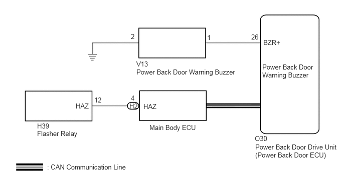
B443295E01
2.719,0.677 2.875,0.875 0.156,0.198 10 false 2 4.302,0.698 4.458,0.896 0.156,0.198 10 false 1 2.833,1.25 3.177,1.417 0.344,0.167 10 false V13 2.833,1.417 5.052,1.625 2.219,0.208 10 false Power Back Door Warning Buzzer 5.219,0.688 5.438,0.885 0.219,0.198 10 false 26 5.469,0.802 6.177,1 0.708,0.198 10 false BZR+ 5.448,1.313 6.563,1.698 1.115,0.385 10 false Power Back Door Warning Buzzer 5.292,2.802 6,3 0.708,0.198 10 false O30 5.302,2.979 7.01,3.323 1.708,0.344 10 false Power Back Door Drive Unit (Power Back Door ECU) 2.979,2.135 3.688,2.333 0.708,0.198 10 false HAZ 2.688,2.125 3,2.323 0.313,0.198 10 false H2 2.719,1.958 3.031,2.156 0.313,0.198 10 false 4 1.958,2 2.271,2.198 0.313,0.198 10 false 12 1.573,2.125 2.281,2.323 0.708,0.198 10 false HAZ 0.771,2.542 1.479,2.74 0.708,0.198 10 false H39 0.771,2.698 1.865,2.917 1.094,0.219 10 false Flasher Relay 0.979,3.396 2.917,3.625 1.938,0.229 10 false : CAN Communication Line 3.104,2.573 4.313,2.792 1.208,0.219 10 false Main Body ECU

PROCEDURE

1.CHECK OPERATION
a.

Check the power back door system operation.

Result
Result Proceed to
Power back door functions but the power back door warning buzzer does not operate. A
Power back door functions but the hazard warning light does not come on. B
Power back door functions but the power back door warning buzzer in the power back door ECU does not operate. C


A

2.PERFORM ACTIVE TEST USING TECHSTREAM

B

6.CHECK WIRELESS DOOR LOCK CONTROL SYSTEM (HAZARD ANSWER-BACK FUNCTION)

C

REPLACE POWER BACK DOOR DRIVE UNIT (POWER BACK DOOR ECU)

2.PERFORM ACTIVE TEST USING TECHSTREAM
a.

Connect the Techstream to the DLC3.


b.

Turn the ignition switch to ON.


c.

Turn the Techstream on.


d.

Enter the following menus: Body Electrical / Back Door / Active Test /


e.

According to the display on the Techstream, perform the Active Test.

Back Door
Tester Display Test Part Control Range Diagnostic Note
PBD Buzzer Power back door buzzer sound ON/OFF -

OK:

Buzzer sounds normally.


OK

REPLACE POWER BACK DOOR DRIVE UNIT (POWER BACK DOOR ECU)

NG

3.REPLACE POWER BACK DOOR WARNING BUZZER
a.

Temporarily replace the power back door buzzer with a new or normally functioning one (See page Vehicle Exterior>DOOR / HATCH>POWER BACK DOOR WARNING BUZZER>REMOVAL).


NEXT

4.CHECK POWER BACK DOOR WARNING BUZZER (OPERATION)
a.

Check that the buzzer sounds operation.


OK:

The buzzer sounds.


NOTICE:

When battery voltage is directly applied to the buzzer does not sound.


OK

END

NG

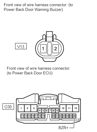
5.CHECK HARNESS AND CONNECTOR (WARNING BUZZER - BACK DOOR ECU AND GROUND)
a.
B443296E01
0.542,1.531 0.938,1.74 0.396,0.208 0.094,3.667 0.49,3.875 0.396,0.208 2.458,4.531 2.615,4.531 2.615,4.531 2.646,4.146 true 0.135,0.083 2.604,0.438 2.469,0.354 10 false Front view of wire harness connector: (to Power Back Door Warning Buzzer) 0.615,1.573 0.958,1.792 0.344,0.219 10 false V13 0.24,2.333 2.521,2.688 2.281,0.354 10 false Front view of wire harness connector: (to Power Back Door ECU) 0.156,3.698 0.5,3.917 0.344,0.219 10 false O30 2.073,4.438 2.625,4.667 0.552,0.229 10 false BZR+

Disconnect the V13 buzzer connector.


b.

Disconnect the O30 ECU connector.


c.

Measure the resistance according to the value(s) in the table below.

Standard Resistance:
Tester Connection Condition Specified Condition
V13-1 - O30-26 (BZR+) Always Below 1 Ω
V13-2 - Body ground Always Below 1 Ω
V13-1 - Body ground Always 10 kΩ or higher


d.

Reconnect the buzzer connector.


e.

Reconnect the ECU connector.


OK

REPLACE POWER BACK DOOR DRIVE UNIT (POWER BACK DOOR ECU)

NG

REPAIR OR REPLACE HARNESS OR CONNECTOR

6.CHECK WIRELESS DOOR LOCK CONTROL SYSTEM (HAZARD ANSWER-BACK FUNCTION)
a.

Check the wireless door lock operation.

OK:

Hazard answer-back function operates normally.


OK

7.REPLACE POWER BACK DOOR DRIVE UNIT (POWER BACK DOOR ECU)

NG

GO TO OTHER FLOW CHART (NO ANSWER - BACK)

7.REPLACE POWER BACK DOOR DRIVE UNIT (POWER BACK DOOR ECU)
a.

Replace the power back door drive unit (power back door ECU) (See page Vehicle Exterior>DOOR / HATCH>POWER BACK DOOR DRIVE UNIT>REMOVAL).


NEXT

8.CHECK POWER BACK DOOR DRIVE UNIT (POWER BACK DOOR ECU)
a.

Check that the power back door warning buzzer operates normally.

OK:

It operates normally.


OK

END (POWER BACK DOOR DRIVE UNIT (POWER BACK DOOR ECU) DEFECTIVE)

NG

REPLACE MAIN BODY ECU (COWL SIDE JUNCTION BLOCK LH)