 |
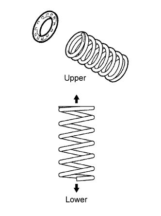
Install the insulator upper LH to the coil spring rear LH.
REAR COIL SPRING > INSTALLATION |
| 1. INSTALL REAR COIL SPRING INSULATOR UPPER LH |
|
Install the insulator upper LH to the coil spring rear LH.
| 2. INSTALL COIL SPRING REAR LH |
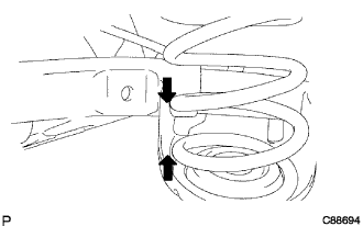 |
Apply a shop rug to the rear axle beam assembly.
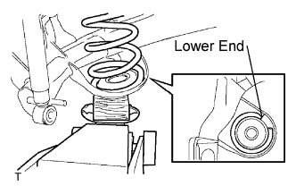 |
Install the coil spring rear LH to the rear axle beam assembly.
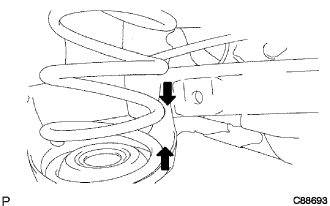 |
Apply a shop rug to the rear axle beam assembly.
| 3. CONNECT SHOCK ABSORBER ASSEMBLY REAR LH |
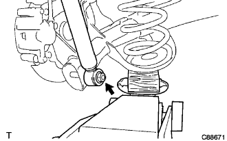 |
While raising the jack, connect the shock absorber assembly rear LH to the rear axle beam assembly.
Temporarily tighten the nut.
| 4. CONNECT SHOCK ABSORBER ASSEMBLY REAR RH |
| 5. CONNECT REAR BRAKE TUBE NO.2 |
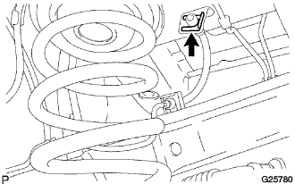 |
Install the flexible hose and clip.
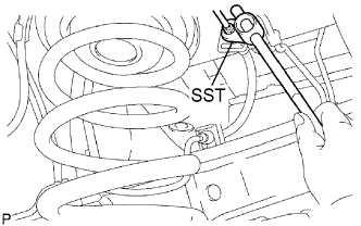 |
Using SST, connect the brake tube to the flexible hose.
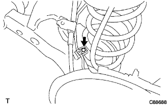 |
Install the bolt.
| 6. CONNECT REAR BRAKE TUBE NO.1 |
| 7. INSTALL PARKING BRAKE CABLE ASSEMBLY NO.3 |
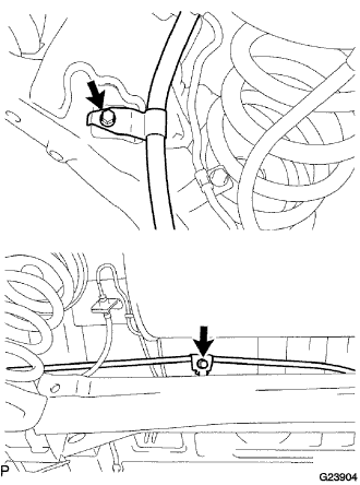 |
Install the 2 bolts and parking brake cable assembly No.3 to the rear axle beam assembly.
| 8. INSTALL PARKING BRAKE CABLE ASSEMBLY NO.2 |
| 9. INSTALL DIFFERENTIAL CARRIER ASSEMBLY REAR (for 4WD) |
| 10. INSTALL REAR DRIVE SHAFT ASSEMBLY LH (for 4WD) |
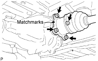 |
Install the rear drive shaft assembly LH, 4 washers and 4 nuts.
| 11. INSTALL REAR DRIVE SHAFT ASSEMBLY RH (for 4WD) |
| 12. INSTALL PROPELLER W/CENTER BEARING SHAFT ASSEMBLY (for 4WD) |
| 13. INSTALL SPEED SENSOR REAR LH (for 4WD) |
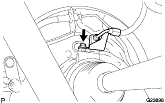 |
Install the speed sensor rear LH and bolt.
| 14. INSTALL SPEED SENSOR REAR RH (for 4WD) |
| 15. CONNECT SKID CONTROL SENSOR WIRE (for 2WD) |
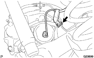 |
Connect the skid control sensor connector.
Install the bolt and bracket to the rear axle beam assembly.
| 16. INSTALL EXHAUST PIPE ASSEMBLY TAIL |
| 17. BLEED BRAKE LINE |
| 18. INSPECT BRAKE FLUID LEVEL IN RESERVOIR |
| 19. STABILIZE SUSPENSION |
Install the rear wheel and jack down the vehicle.
Bounce the vehicle up and down several times to stabilize the suspension.
| 20. FULLY TIGHTEN SHOCK ABSORBER ASSEMBLY REAR LH |
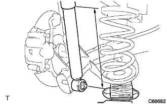 |
Stabilize the shock absorber assembly rear LH.
If it is impossible to tighten the nut at this position, support the rear axle beam assembly with a jack and load the rear compartment with a mass of approximately 90 kg (198 lb).
|
Fully tighten the nut.
| 21. FULLY TIGHTEN SHOCK ABSORBER ASSEMBLY REAR RH |
| 22. FULLY TIGHTEN REAR AXLE BEAM ASSEMBLY |
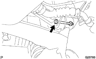 |
Stabilize the rear axle beam assembly.
Fully tighten the bolt.
| 23. INSTALL REAR FLOOR NO.2 CROSSMEMBER BRACE LH |
Install the floor No.2 crossmember brace and 2 bolts.
| 24. INSTALL REAR FLOOR NO.2 CROSSMEMBER BRACE RH |
| 25. INSTALL FUEL TANK FILLER HOSE COVER |
Install the fuel tank filler pipe protector, 2 bolts, 3 screws and 3 nuts.
Install the fuel tank filler hose cover and 3 bolts.
| 26. INSPECT REAR WHEEL ALIGNMENT |
| 27. CHECK ABS SPEED SENSOR SIGNAL |
ABS WITH EBD SYSTEM (Click here)
ABS WITH EBD & BA & TRAC & VSC SYSTEM (Click here)