MAINTENANCE REAR DISC BRAKE PAD REMOVAL
CAUTION / NOTICE / HINT
- CAUTION:
- ·
Vehicle may slip off the vehicle hoist if the vehicle hoist is handled incorrectly.
Danger! Life-threatening injuries!
-Observe safety information on raising the vehicle using a vehicle hoist.
-For additional information see:
Click hereGeneral>INTRODUCTION>REPAIR INSTRUCTION>VEHICLE LIFT AND SUPPORT LOCATIONS
·Effects on other persons.
Danger of injury! Risk of damage!
-Make sure that no other persons are in or around the vehicle.
- NOTICE:
- ·
General information on changing the brake pads:
-For vehicles older than 48 months it is recommended to replace the retaining spring or expanding spring.
-The pad wear indicator wire RH must be replaced once it has been removed because the pad wear indicator wire RH loses its retention capability in the brake pad.
·A CBS reset must be done after every brake pad exchange:
-A CBS reset in the vehicle is possible in the event of a partially ground down pad wear indicator wire RH. The CBS display in the multi-display is active.
-In the event of a pad wear indicator wire RH that is not partially ground down, a CBS reset is only possible with the diagnosis system. No CBS display in the multi-display.
Click hereGeneral>INTRODUCTION>REPAIR INSTRUCTION>CONDITION BASED SERVICE (CBS)
·During work on the rear brake, it must be ensured that the button for the electromechanical parking brake cannot be pressed.
·When exchanging brake pads, reset the CBS display in accordance with factory specification (CBS reset).
·Carry out test braking while driving at low speed because the effectiveness of the brakes may be reduced during the initial braking operations.
·Exaggerated emergency and continuous braking operations for faster bedding-in are not permitted.
·Advise the customer not to perform intentional emergency braking operations for the first 200 km (124 mile) after the brakes have been replaced.
- HINT:
- ·
The following procedure is for the LH side.
·Use the same procedure for the RH side and LH side.
PROCEDURE

 1.PERFORM REAR BRAKE PAD REPLACEMENT MODE
Connect the diagnosis system with the vehicle.
Determine the workshop mode.
Vehicle management / Service functions / Chassis / Parking brake / Workshop mode
Disconnect the diagnosis system from the vehicle.
2.REMOVE REAR WHEEL
3. MEASURE MINIMUM BRAKE DISC THICKNESS
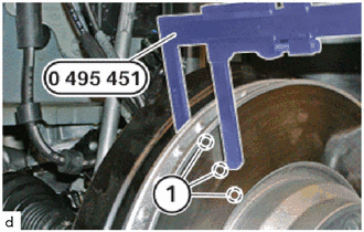
Place the special tool 0 495 451 (34 1 280) at three measuring points in area (1) and measure.
- SST
- 09700-WA090
Compare the measuring results and compare the lowest value with the setpoint value.
- HINT:
-
New rear disc brake pads must only be installed if the rear disc thickness is greater than the minimum rear disc thickness.
- Minimum brake disc thickness:
- Nominal dimension 330x20:
18.4 mm (0.724 in.)
- Nominal dimension 345x24:
22.4 mm (0.882 in.)
4.REMOVE PAD WEAR INDICATOR WIRE RH (for RH Side)
- HINT:
- ·
The pad wear indicator wire RH must be replaced once it has been removed because the pad wear indicator wire RH loses its retention capability in the rear disc brake pad.
·If a pad wear indicator wire RH that has already been ground has to be replaced even though the minimum rear disc brake pad thickness has not yet been reached, you must observe the following:
-The new sliding contact must be filed down with a file to the same length as the sanded sliding contact.
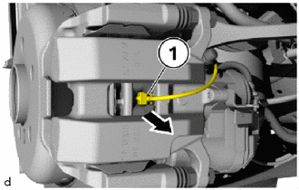
Remove the pad wear indicator wire RH (1) from the rear disc brake pad in the direction of the arrow.
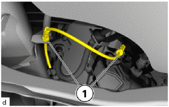
Detach the cable of the pad wear indicator wire RH from the brackets (1).
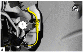
Detach the cable of the pad wear indicator wire RH from the brackets (1).
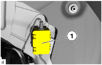
Open the connection box (1).
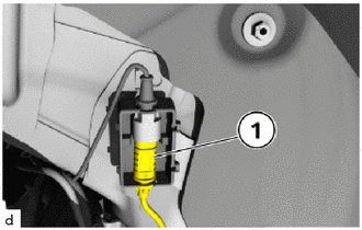
Unlock plug connection (1) and disconnect.
Remove pad wear indicator wire RH.
5.REMOVE REAR DISC BRAKE PAD
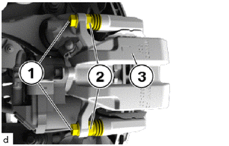
Release the 15 mm bolts (1), if necessary use the hexagon head (2) for counter support.
Remove rear disc brake cylinder assembly (3).
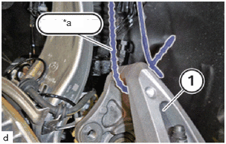
| *a | Rope |
Tie up the rear disc brake cylinder assembly (1) with the rope.
- NOTICE:
-
Do not hang the rear disc brake cylinder assembly from the rear flexible hose.
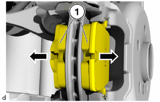
Remove the rear disc brake pad (1) in the direction of the arrows.
Mark any worn brake pads.
- HINT:
-
If the rear disc brake pad wear exists on one side, they must not be mixed up.
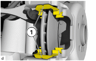
Remove the rear disc brake pad support plates (1).
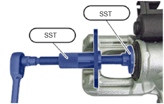
Press back the brake piston using the SST.
- SST
- 09719-12010