MAINTENANCE REAR DISC BRAKE PAD INSTALLATION
CAUTION / NOTICE / HINT
- HINT:
- ·
Use the same procedure for the RH side and LH side.
·The following procedure is for the LH side.
PROCEDURE

 1.INSTALL REAR DISC BRAKE PAD
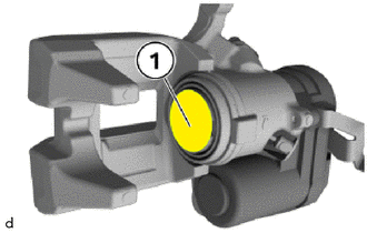
Clean the contact surface (1) of the rear disc brake piston with brake cleaner and apply a thin coat of brake pad paste.
Check the cylinder boot for damage and replace if necessary.
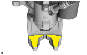
Clean the contact surface of the rear disc brake cylinder assembly with brake cleaner and apply a thin coat of brake pad paste.
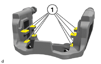
Clean the contact surface (1) of the rear disc brake cylinder mounting with brake cleaner and apply a thin coat of brake pad paste.
- NOTICE:
-
Do not mechanically clean the contact surfaces (1) for the rear disc brake pad support plates at the rear disc brake cylinder mounting to prevent damage to the surface coating.
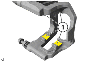
Clean the contact surface (1) of the rear disc brake cylinder mounting with brake cleaner and apply a thin coat of brake pad paste.
- NOTICE:
-
Do not mechanically clean the contact surfaces (1) for the rear disc brake pad support plates at the rear disc brake cylinder mounting to prevent damage to the surface coating.
Install the rear disc brake pad support plates.
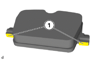
Coat the T-head of outer rear disc brake pad in the marked area (1) in each case with a thin coating of brake pad paste.
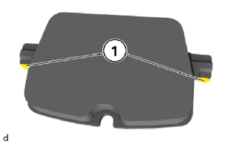
Coat the T-head of outer rear disc brake pad in the marked area (1) in each case with a thin coating of brake pad paste.
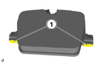
Coat the T-head of outer rear disc brake pad in the marked area (1) in each case with a thin coating of brake pad paste.
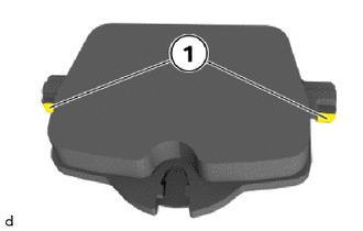
Coat the T-head of outer rear disc brake pad in the marked area (1) in each case with a thin coating of brake pad paste.
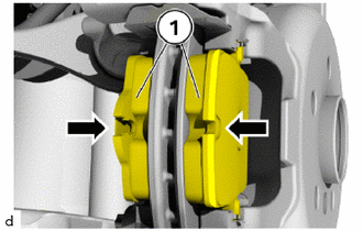
Install the rear disc brake pads (1) in the direction of the arrows.
Detach the rear disc brake cylinder assembly from the rope and position on the rear disc brake cylinder assembly.
Replace 15 mm bolts.
Tighten the 15 mm bolts, if applicable, hold against the hexagon head.
- Torque:
- 35 N*m (357 kgf*cm, 26 ft.*lbf)
2.INSTALL PAD WEAR INDICATOR WIRE RH (for RH Side)
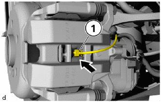
Replace the pad wear indicator wire RH (1).
Insert the pad wear indicator wire RH (1) into the rear disc brake pad in the direction of the arrow.
- HINT:
-
Ensure pad wear indicator wire RH (1) fits correctly in rear disc brake pad.
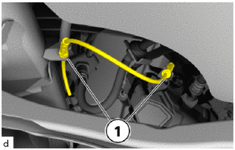
Attach cable of pad wear indicator wire RH in brackets (1).
Attach cable of pad wear indicator wire RH in brackets (1).
Connect connectors and lock.
Close the connection box.
3.INSTALL REAR WHEEL
4. NORMAL CONDITION RECOVERY
Connect the diagnosis system with the vehicle.
Cancel the workshop mode.
Vehicle management / Service functions / Chassis / Parking brake / Workshop mode
Disconnect the diagnosis system from the vehicle.
5. START-UP OR BEDDING-IN OF NEW BRAKE PADS AND DISCS
- NOTICE:
- ·
When exchanging brake pads, reset the CBS display in accordance with factory specification (CBS reset).
·Carry out test braking while driving at low speed because the effectiveness of the brakes may be reduced during the initial braking operations.
·Exaggerated emergency and continuous braking operations for faster bedding-in are not permitted.
·Advise the customer not to perform intentional emergency braking operations for the first 200 km (124 mile) after the brakes have been replaced.
Fully depress brake pedal several times so that brake pads contact brake discs.
Use the parking brake button to open, close and open the parking brake again.
Adjust the brake fluid level to the maximum mark.
Perform a functional check on the brake test stand to ensure compliance of the brake system with statutory guidelines.
6. PERFORM CBS RESET