HEATING / AIR CONDITIONING REFRIGERANT REPLACEMENT
RECOVER REFRIGERANT FROM REFRIGERATION SYSTEM
- CAUTION:
- ·
Refrigerant circuit under high pressure.
Danger of injury.
-Note and follow safety information on containers.
-Avoid contact with refrigerant; wear safety goggles and protective gloves.
-For more information see:
*Handling refrigerant:
Click hereVehicle Interior>HEATING / AIR CONDITIONING>REFRIGERANT>PRECAUTION
*Notes on repair work on air conditioning:
Click hereVehicle Interior>HEATING / AIR CONDITIONING>AIR CONDITIONING SYSTEM>PRECAUTION
- NOTICE:
-
The engine is switched off.
- HINT:
-
Collect and dispose of emerging fluids. Observe country-specific waste disposal regulations.
Let the engine run for a few minutes at a low engine speed (800 to 1200 rpm) and with the heating and air conditioning system switched on.
Stop engine.
Remove the service valve caps from the service valves.
Connect the high pressure line of the refrigerant recovery unit with the vehicle's high-pressure connection.
Connect the low-pressure line of the refrigerant recovery unit with the vehicle's low-pressure connection.
Start the evacuation on the refrigerant recovery unit.
During evacuation, allow the blower of the heating and air conditioning unit to run at middle blower speed.
Record the amount of evacuated refrigerant and amount of compressor oil after having completed evacuation.
Keep the sheet with the recorded quantities as the values are once again required when filling.
Disconnect the high pressure line and low pressure line.
Drain the high pressure line and low pressure line.
Close the service valve caps of the service valves.
Correctly dispose of the drained compressor oil.
CHARGE AIR CONDITIONING SYSTEM WITH REFRIGERANT
- CAUTION:
- ·
Refrigerant circuit under high pressure.
Danger of injury.
-Note and follow safety information on containers.
-Avoid contact with refrigerant; wear safety goggles and protective gloves.
-For more information see:
*Handling refrigerant:
Click hereVehicle Interior>HEATING / AIR CONDITIONING>REFRIGERANT>PRECAUTION
*Notes on repair work on air conditioning:
Click hereVehicle Interior>HEATING / AIR CONDITIONING>AIR CONDITIONING SYSTEM>PRECAUTION
- NOTICE:
- ·
The engine is switched off.
·The vehicle is on the floor.
- HINT:
-
Filling a raised vehicle will result in insufficient filling levels.
Remove the service valve caps from the service valves.
Connect the high pressure line of the vacuum pump or appropriate equipment with the vehicle's high-pressure connection.
Connect the low-pressure line of the vacuum pump with the vehicle's low-pressure connection.
Start the evacuation on the vacuum pump.
Adhere to an evacuation time of at least 30 min.
During evacuation, allow the blower of the heating and air conditioning unit to run at middle blower speed.
If the vacuum does not remain stable during evacuation:
Run the inspect for leaks in the refrigerant circuit.
Rectify leaks in the refrigerant circuit.
Determine the quantities of a new compressor oil to be refilled.
In addition to the drawn off and recorded amount of compressor oil, add the following quantities (if applicable).
Top up the compressor oil losses over time as per the table.
Table 1 indicates the permitted loss of refrigerant after a specific period of time. There is no leak. Compressor oil must not be topped up.
Table 2 indicates the amount of compressor oil which must be topped up after a specific period of time with an impermissible loss of refrigerant due to a leak.
Case 1: Refrigerant loss is not exceeded as per Table 1.
Top up missing refrigerant.
It is not permitted to top up the compressor oil.
Case 2: Refrigerant loss is exceeded as per Table 1.
Top up missing refrigerant.
Compressor oil must be topped up additionally according to Table 2.
| No. of years since the last filling | 0 to 1 | 1 to 2 | 2 to 3 | 3 to 4 | 4 to 5 |
| Permissible loss (Do not top up compressor oil) | below 30 g (1.1 oz) | below 60 g (2.1 oz) | below 90 g (3.2 oz) | below 120 g (4.2 oz) | below 150 g (5.3 oz) |
| No. of years since the last filling | Loss of refrigerant | Top up quantity compressor oil |
| 0 to 1 | 120 g (4.23 oz) or less | 0 |
| 120 to 150 g (4.23 to 5.29 oz) | 10 cc (0.338 fl.oz) | |
| 150 g (5.29 oz) or higher | 20 cc (0.676 fl.oz) | |
| 1 to 2 | 180 g (6.35 oz) or less | 0 |
| 180 to 210 g (6.35 to 7.41 oz) | 10 cc (0.338 fl.oz) | |
| 210 g (7.41 oz) or higher | 20 cc (0.676 fl.oz) | |
| 2 to 3 | 240 g (8.47 oz) or less | 0 |
| 240 to 270 g (8.47 to 9.52 oz) | 10 cc (0.338 fl.oz) | |
| 270 g (9.52 oz) or higher | 20 cc (0.676 fl.oz) | |
| 3 to 4 | 300 g (10.6 oz) or less | 0 |
| 300 to 330 g (10.6 to 11.6 oz) | 10 cc (0.338 fl.oz) | |
| 330 g (11.6 oz) or higher | 20 cc (0.676 fl.oz) | |
| 4 to 5 | 360 g (12.7 oz) or less | 10 cc (0.338 fl.oz) |
| 360 g (12.7 oz) or higher | 20 cc (0.676 fl.oz) |
Add compressor oil according to the table if parts of the refrigerant circuit have been replaced.
Case 1: Part exchange as preliminary work for additional work and part exchange due to slow leakage (minor leak, e.g. hairline crack).
Case 2: Part exchange due to sudden leakage (major leak, e.g. line disconnection caused by accident).
|
*1: Oil the compressor with pulley assembly. |
||
| Parts | Case 1 | Case 2 |
| Compressor with pulley assembly*1 | * | * |
| Evaporator | 10 cc (0.338 fl.oz) | 35 cc (1.18 fl.oz) |
| Parts | Case 1 | Case 2 |
| Cooler condenser assembly | 40 cc (1.35 fl.oz) | 55 cc (1.86 fl.oz) |
| For each replaced refrigerant line | 10 cc (0.338 fl.oz) | 35 cc (1.18 fl.oz) |
| Per replaced air conditioner pressure sensor | 0 | 0 |
| Per replaced seal | 0 | 0 |
Top up determined amount of compressor oil into the refrigerant circuit.
Fill the amount of refrigerant as per the type plate into the refrigerant circuit.
Disconnect the high pressure line and low pressure line on the vehicle.
Drain the high pressure line and low pressure line.
Close the service valves on the vehicle with the service valve caps.
- Standard Charge Amount:
HFC-134a(R134a): 550 g (19.4 oz)
HFO-1234yf (R1234yf): 550 g (19.4 oz)
- SST
- 09985-20010 (09985-02010, 09985-02050, 09985-02060, 09985-02070, 09985-02080, 09985-02090, 09985-02110, 09985-02130, 09985-02140, 09985-02150)
INSPECT FOR REFRIGERANT LEAK
After recharging the air conditioning system with refrigerant, inspect for refrigerant leaks using a halogen leak detector.
- HINT:
- ·
for HFO-1234yf (R1234yf):
-Be sure to use a halogen leak detector that is compatible with HFO-1234yf (R1234yf) systems.
Carry out the test under the following conditions:
Check that the START-STOP button (engine switch) off.
- HINT:
-
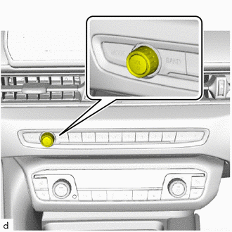
-
Pressing and holding the AUDIO button changes the power source mode to IG OFF.
Ensure good ventilation (the halogen leak detector may react to volatile gases which are not refrigerant, such as gasoline vapor and exhaust gas).
Repeat the inspection 2 or 3 times.
Measure the pressure to make sure that there is some refrigerant remaining in the air conditioning system.
Pressure when the compressor is off: approximately 392 to 588 kPa (3.9 to 5.9 kgf/cm2, 57 to 85 psi)
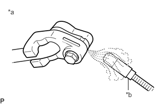
| *a | Inspect for Leak |
| *b | Halogen Leak Detector |
Using a halogen leak detector, inspect for refrigerant leaks from the air conditioning system.
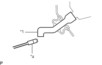
| *1 | Drain Cooler Hose |
| *a | Halogen Leak Detector |
Bring the halogen leak detector close to the drain cooler hose with the detector power off, and then turn the detector on.
- HINT:
- ·
After the blower motor has stopped, leave the cooling unit for more than 15 minutes.
·Bring the halogen leak detector sensor under the drain cooler hose.
·When bringing the halogen leak detector close to the drain cooler hose, make sure that the halogen leak detector does not react to volatile gases. If it is not possible to avoid interference from volatile gases, the vehicle should be lifted up to allow checking for leaks.
If a refrigerant leak is not detected from the drain cooler hose, remove the blower motor control from the cooling unit. Insert the halogen leak detector sensor into the unit and check for leaks.
Disconnect the pressure sensor connector and leave it for approximately 20 minutes. Bring the halogen leak detector close to the pressure sensor and check for leaks.
- HINT:
-
When checking for leaks, the presence of oily dirt at a joint can indicate a leak.