8HP51 AUTOMATIC TRANSMISSION / TRANSAXLE TRANSMISSION VALVE BODY INSTALLATION
PROCEDURE

 1.INSTALL MECHATRONICS
- NOTICE:
- ·
Damage on the automatic transmission assembly after removing the mechatronics.
Non-observance of the following work may cause severe damage to the automatic transmission assembly.
-Load specific data status with the diagnosis system.
Vehicle information / Control unit list / EGS / Call up control unit functions / Diagnostic request / EGS sensor / Parking lock position
-Use only the approved Automatic Gearbox Oil ATF 3+.
-After completion of repair work, check the automatic transmission fluid level.
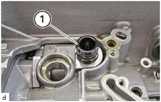
Replace the pressure pipe (1).
Coat the O-rings at the new pressure pipe using ATF.
Install pressure pipe (1).
Fit mechatronics unit.
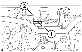
Feed shifting claw (1) into gearshift shaft (2).
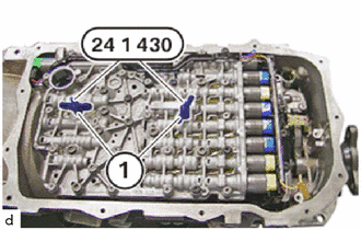
Install mechatronics.
Alternately tighten the wing nuts (1) of special tool 0 496 715 (24 1 430) until the mechatronics are in contact with the automatic transmission assembly.
- SST
- 09300-WA080
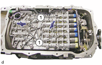
Insert the T40 bolts (1) and tighten lightly.
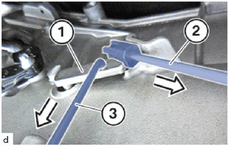
Pull the selector shaft journal (1) downward with the special tool 2 355 850 (3) in the direction of the arrow.
- SST
- 09700-WA050
Remove the special tool 2 355 850 (2) in the direction of the arrow.
- SST
- 09700-WA050
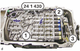
Carefully position the output speed sensor (3) and push it in up to the limit position.
- SST
- 09700-WA050
- HINT:
- ·
Note the original mounting orientation of the output speed sensor.
·Observe the correct mounting orientation when installing the output speed sensor.
·The journal on the output speed sensor may break off during removal or installation.
Insert the T40 bolts (2) and tighten lightly.
Release the wing nuts (1).
Remove special tool 0 496 715 (24 1 430).
- SST
- 09300-WA080
Insert the T40 bolts (1) and tighten lightly.
Replace the sealing sleeve (1).
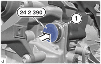
Carefully position the sealing sleeve (1).
Twist the sealing sleeve (1) until the lug has been inserted into the groove of the gear.
Slide in the sealing sleeve (1) in the direction of the arrow up to the limit position.
- NOTICE:
-
The lug on the sealing sleeve must not be damaged.
Remove special tool 0 494 213 (24 2 390).
- SST
- 09300-WA100
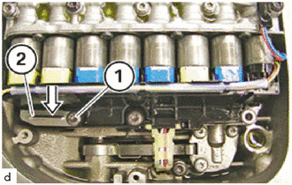
Push the slide (2) in the direction of the arrow and lock.
Replace the T40 bolt (1).
Screw in the T40 bolt (1).
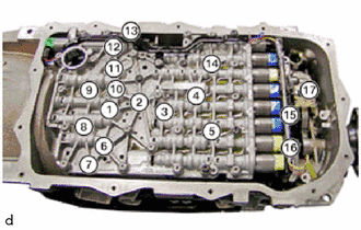
Replace T40 bolts.
- NOTICE:
- ·
When assembling, it is essential to observe screwing sequences and tightening torques.
·Non-compliance with the regulations can lead to damage.
Tighten the T40 bolts in the order (1) to (16).
- Torque:
- 8.0 N*m (82 kgf*cm, 71 in.*lbf)
Tighten the T40 bolt (17) of the output speed sensor.
- Torque:
- 4.0 N*m (41 kgf*cm, 35 in.*lbf)
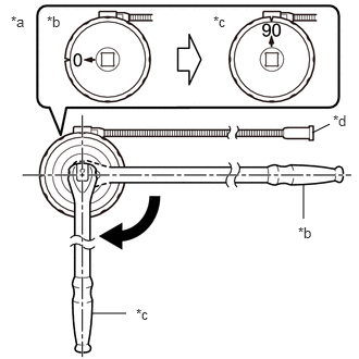
Using SST, tighten the T40 bolt an additional 12°.
- SST
- 09900-WA010
- HINT:
- ·
 2.99,1.271 3.156,1.188 false 2.906,2.094 2.906,1.76 false 0.875,3 1.208,3 false 0.104,0.125 0.417,0.281 0.313,0.156 10 false *a 0.448,0.125 0.76,0.281 0.313,0.156 10 false *b 2.042,0.125 2.354,0.281 0.313,0.156 10 false *c 3.188,1.073 3.427,1.271 0.24,0.198 10 false *d 2.854,2.146 3.167,2.302 0.313,0.156 10 false *b 1.302,2.927 1.615,3.083 0.313,0.156 10 false *c
*a Example *b Before Tightening *c After Tightening *d Magnetic Portion
·The magnetic portion is used to secure the gauge to the vehicle.
·After first adjusting the needle of the gauge to 0°, tighten to the specified angle.
·Perform the work procedure carefully so that the gauge, etc. does not become tilted.
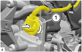
Slide the connector (1) on.
Twist the connector (1) in the direction of the arrow and lock.
2.INSTALL HYDRAULIC IMPULSE STORAGE
3.INSTALL TRANSMISSION OIL SUMP
- HINT:
-
The transmission oil sump must be replaced each time it is released.
Clean the contact surface of the transmission oil sump on the automatic transmission assembly.
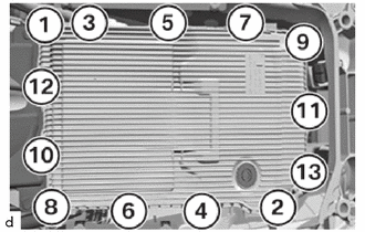
Replace T40 bolts (1) to (13).
Position the transmission oil sump.
Insert T40 bolts until screw heads make contact.
Tighten T40 bolts in the order (1) to (13).
- Torque:
- 10 N*m (102 kgf*cm, 7 ft.*lbf)
If necessary, tighten the oil drain plug.
- Torque:
- 8.0 N*m (82 kgf*cm, 71 in.*lbf)
4.CONNECT CABLE TO NEGATIVE BATTERY TERMINAL (for B48)
5.CONNECT CABLE TO NEGATIVE BATTERY TERMINAL (for B58)
6.ADJUST AUTOMATIC TRANSMISSION FLUID LEVEL
7.INSPECT FOR AUTOMATIC TRANSMISSION FLUID LEAK
50819
8.INSTALL FRONT FLOOR COVER