REAR SUSPENSION REAR COIL SPRING REMOVAL
CAUTION / NOTICE / HINT
- CAUTION:
- ·
Vehicle may slip off the vehicle hoist if the vehicle hoist is handled incorrectly.
Danger! Life-threatening injuries!
-Observe safety information on raising the vehicle using a vehicle hoist.
-For additional information see:
Click hereGeneral>INTRODUCTION>REPAIR INSTRUCTION>VEHICLE LIFT AND SUPPORT LOCATIONS
- HINT:
- ·
Use the same procedure for the RH side and LH side.
·The following procedure is for the LH side.
PROCEDURE

 1.REMOVE REAR WHEEL
48738
2.REMOVE REAR SUSPENSION ARM COVER
3.REMOVE REAR COIL SPRING
- CAUTION:
- ·
Spring preload.
Danger! Life-threatening injuries!
-Secure coil spring with special tool 2 213 022 (31 3 340).
-Use special tool as per owner's handbook and always observe the safety information.
- NOTICE:
- ·
Do not operate special tool with an impact screwdriver.
·Incorrect assembly is possible.
Ensure correct installation position.
- HINT:
- ·
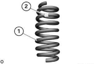
The installation position of the rear coil spring (1) is marked with a label (2).
-The label (2) is attached at the top end of the rear coil spring (1) and is marked as "top".
·Check rear coil spring (1) for availability of label (2).
-If the label (2) on the installed rear coil spring (1) is missing and it has to be fixed after repair, then the installation position of the rear coil spring (1) must be marked necessarily.
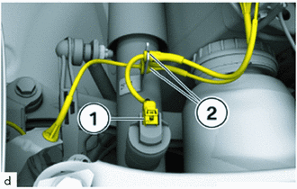
w/ AVS:
Unlock plug connection (1) and disconnect.
Detach lines (2) from the holder.
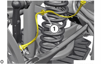
Release the rear skid control sensor wire (1) from the holder on rear shock absorber assembly.
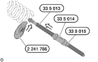
Insert lower spring cup 2 241 786 centrally into rear coil spring and turn to lowest winding.
- SST
- 09700-WA180
Drive spindle 0 494 994 (33 5 013), 0 494 995 (33 5 014), 0 494 996 (33 5 015) from below through the rear No. 2 suspension arm assembly and the bottom spring cup 2 241 786.
- SST
- 09700-WA160
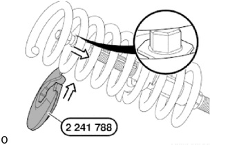
Insert top spring cup 2 241 788 sideways into rear coil spring and turn to the uppermost winding.
- SST
- 09700-WA180
- NOTICE:
-
Make sure spindle (hexagonal) is correctly seated in upper spring cup 2 241 788.
Pull spindle 0 494 994 (33 5 013) down.
- NOTICE:
-
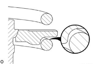
-
Make sure rear coil spring is correctly positioned in spring cups.
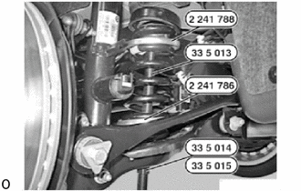
Check and correct the position of the special tools 2 241 786, 2 241 788 and 0 494 994 (33 5 013), 0 494 995 (33 5 014), 0 494 996 (33 5 015) and correct if required.
- SST
- 09700-WA160
09700-WA180
- NOTICE:
-
The special tools must be aligned centrally, in order to obtain the largest possible contact surface on the rear coil spring.
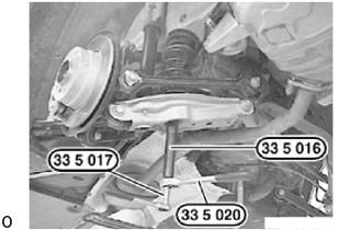
Tensioning the rear coil spring using the special tools 0 494 997 (33 5 016) and 0 494 934 (33 5 020).
- SST
- 09700-WA160
09700-WA180
- HINT:
-
Counter support the spindle of the spring tensioner with the special tool 0 494 998 (33 5 017).
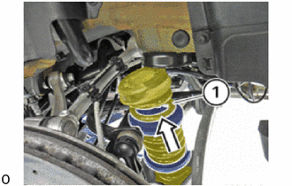
Remove rear coil spring (1) upwards.
Relieve tension on special tool 0 494 933 (33 5 010).
- SST
- 09700-WA160
Remove rear coil spring.
Remove the rear upper coil spring insulator from the rear coil spring.
Remove the rear lower coil spring insulator from the rear No. 2 suspension arm assembly.