B58 FUEL FUEL TANK INSTALLATION
PROCEDURE

 1.INSTALL FUEL TANK
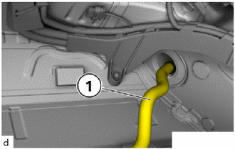
Raise the fuel tank and, while doing so, thread the tank ventilation line (1) through the rear axle support.
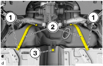
Raise the fuel tank to the installation position, observing the installation position of the tank ventilation line while doing so.
Tighten nut (3).
- Torque:
- 19 N*m (194 kgf*cm, 14 ft.*lbf)
Position the fuel tank band sub-assembly (2) and tighten the screws (1).
- Torque:
- 19 N*m (194 kgf*cm, 14 ft.*lbf)
Secure the fuel tank inlet pipe sub-assembly (2) on the fuel tank.
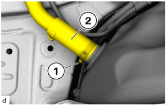
Tighten the hose clamp (1).
- Torque:
- 19 N*m (194 kgf*cm, 14 ft.*lbf)
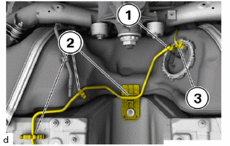
Connect and lock the fuel line (1).
Clip the fuel line (1) into the holder (2).
Connect connectors (3) and lock.
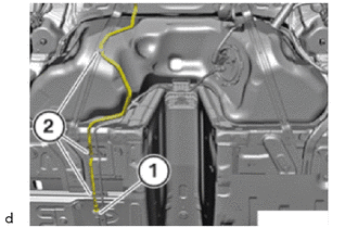
Connect and lock the snap fastener (1).
Clip the tank ventilation line into the holders (2).
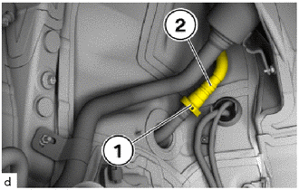
Push on the tank ventilation line (2).
Connect and lock the snap fastener (1).
37100
2.INSTALL PROPELLER SHAFT ASSEMBLY WITH CENTER BEARING
65637
3.INSTALL REAR WHEEL HOUSE LINER RH
- NOTICE:
-
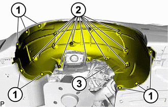
-
To provide a better overview: Schematic diagram with partially hidden components.
Guide the rear wheel house liner RH (3) in.
Tighten the bolts (1) and nuts (2).
- Torque:
- Screw : 2.6 N*m (27 kgf*cm, 23 in.*lbf)
- Nut : 2.6 N*m (27 kgf*cm, 23 in.*lbf)
4.INSTALL WHEEL ASSEMBLY
5. FILLING FUEL TANK WITH FUEL