B48 COOLING FAN SHROUD INSTALLATION
PROCEDURE

 16360A
1.INSTALL FAN WITH MOTOR ASSEMBLY
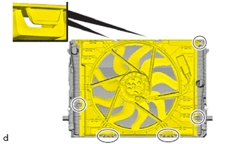
Engage the fan with motor assembly at the guides (marks).
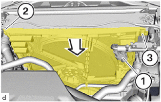
Feed in and install the fan with motor assembly in the direction of the arrow.
Engage the fan with motor assembly in the bracket (3).
Position and tighten the T30 bolt (2).
- Torque:
- 6.0 N*m (61 kgf*cm, 53 in.*lbf)
Connect and lock the connector (1).
The connector (1) must engage audibly.
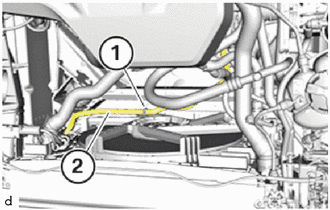
Feed in and install automatic transmission oil cooler tube (2).
Lock clamp (1).
The clamp (1) must engage audibly.
53205
2.INSTALL UPPER RADIATOR SUPPORT SUB-ASSEMBLY
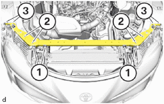
Position upper radiator support sub-assembly.
Insert bolts (1) and tighten them.
- Torque:
- 19 N*m (194 kgf*cm, 14 ft.*lbf)
Insert E14 bolts (2) and tighten.
- Torque:
- 56 N*m (571 kgf*cm, 41 ft.*lbf)
Insert bolts (3) and tighten them.
- Torque:
- 8.0 N*m (82 kgf*cm, 71 in.*lbf)
If applicable, attach the Bowden cables.
Clip in housing in the marked areas.
Position wiring harness.
Mount clips.
53295A
3.INSTALL RADIATOR UPPER AIR DEFLECTOR
52521B
4.INSTALL FRONT BUMPER UPPER RETAINER
53111M
5.INSTALL FRONT BUMPER INNER SUPPORT
81150
6.INSTALL HEADLIGHT ASSEMBLY LH
81110
7.INSTALL HEADLIGHT ASSEMBLY RH
- HINT:
-
Use the same procedure as for the LH side.