EXTERIOR PANELS / TRIM FRONT BUMPER REASSEMBLY
PROCEDURE

 52676
1.INSTALL FRONT BUMPER LOWER SIDE SUPPORT LH
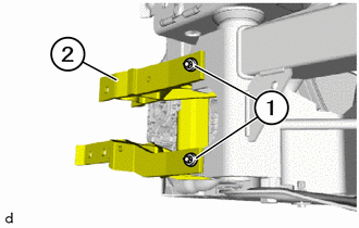
Install the front bumper lower side support LH (2) with E10 bolts (1).
- Torque:
- 19 N*m (194 kgf*cm, 14 ft.*lbf)
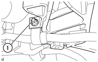
Install the E8 bolt (1).
- Torque:
- 8.0 N*m (82 kgf*cm, 71 in.*lbf)
52675
2.INSTALL FRONT BUMPER LOWER SIDE SUPPORT RH
- HINT:
-
Use the same procedure as for the LH side.
3.INSTALL IMPACT ABSORBER
Replace the blind rivet.
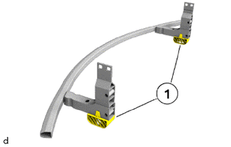
Set the impact absorbers (1).
Mount blind rivets.
52147J
4.INSTALL LOWER FRONT BUMPER REINFORCEMENT
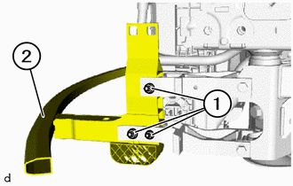
Install the lower front bumper reinforcement (2).
Install the E10 bolts (1).
- Torque:
- 19 N*m (194 kgf*cm, 14 ft.*lbf)
- HINT:
-
Perform the operations on the left and right side.
53212
5.INSTALL RADIATOR SUPPORT LH
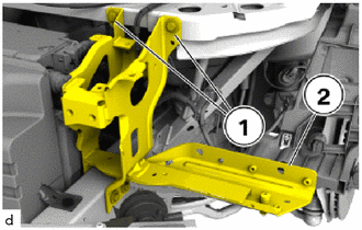
Install the radiator support LH (2) with bolts (1).
- Torque:
- 19 N*m (194 kgf*cm, 14 ft.*lbf)
53211
6.INSTALL RADIATOR SUPPORT RH
- HINT:
-
Use the same procedure as for the LH side.
89174
7.INSTALL AIRBAG SENSOR (w/ Airbag Sensor)
17312
8.INSTALL INLET NO. 2 AIR DUCT
for B48:
Click hereEngine / Hybrid System>B48 (INTAKE / EXHAUST)>INLET AIR DUCT>INSTALLATION
for B58:
Click hereEngine / Hybrid System>B58 (INTAKE / EXHAUST)>INLET AIR DUCT>INSTALLATION
17700
9.INSTALL AIR CLEANER ASSEMBLY
10.INSTALL ENGINE HOOD COURTESY SWITCH (HOOD LOCK ASSEMBLY)
53510
11.INSTALL HOOD LOCK ASSEMBLY
52126
12.INSTALL FRONT BUMPER RETAINER LH
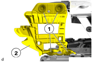
Install the front bumper retainer LH (2) with bolts (1).
- Torque:
- 8.0 N*m (82 kgf*cm, 71 in.*lbf)
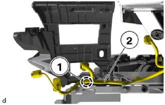
Engage the clamp (1) to connect the No. 4 engine room wire (2).
52125
13.INSTALL FRONT BUMPER RETAINER RH
- HINT:
-
Use the same procedure as for the LH side.
53016
14.INSTALL RADIATOR BRACE ROD SUB-ASSEMBLY
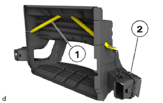
Install the radiator brace rod sub-assembly (1) into the No. 1 cool air intake duct (2).
52811A
15.INSTALL NO. 1 COOL AIR INTAKE DUCT
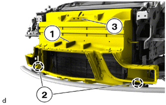
Install the No. 1 cool air intake duct (1) together with the radiator brace rod sub-assembly (3) into the guides (2) and position.
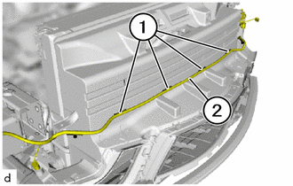
Engage the clamps (1) to connect the No. 4 engine room wire (2).
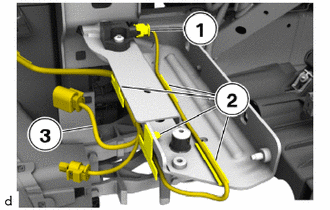
Engage the clamps (2) to connect the No. 4 engine room wire (3).
w/ Airbag Sensor:
Connect the connector (1).
16.INSTALL TEMPERATURE SENSOR ASSEMBLY
52822
17.INSTALL AIR INTAKE DUCT LH
52821
18.INSTALL AIR INTAKE DUCT RH
52115K
19.INSTALL FRONT BUMPER SIDE SUPPORT
- HINT:
-
Description is for left component only. Procedure on the right side is identical.
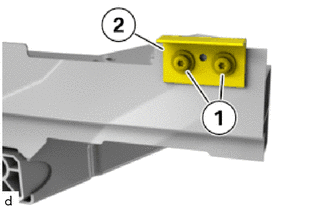
Install the front bumper side support (2) with the T30 bolts (1).
- Torque:
- 8.0 N*m (82 kgf*cm, 71 in.*lbf)
52131A
20.INSTALL FRONT BUMPER REINFORCEMENT
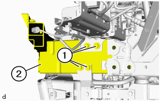
Install the front bumper reinforcement (2).
Install the bolts (1).
- Torque:
- 19 N*m (194 kgf*cm, 14 ft.*lbf)
- HINT:
-
Perform the operations on the left and right side.
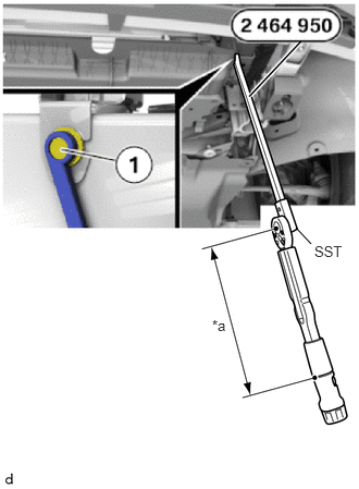
| *a | Torque Wrench Fulcrum Length |
Tighten the bolt (1) with special tool 2 464 950 and SST, a torque wrench.
- SST
- 09800-WA310 09900-WA280
- Torque:
- Specified tightening torque : 19 N*m (194 kgf*cm, 14 ft.*lbf)
- HINT:
- ·
Calculate the torque wrench reading when changing the fulcrum length of the torque wrench.
Click hereGeneral>INTRODUCTION>REPAIR INSTRUCTION>PRECAUTION
·Perform the operations on the left and right side.
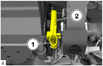
Install the bottom cooler module mount (2) with T30 bolt (1).
- Torque:
- 10 N*m (102 kgf*cm, 7 ft.*lbf)
- HINT:
-
Perform the operations on the left and right side.
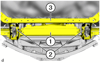
Remove suitable auxiliary materials to disengage the radiator assembly (1) from the upper radiator support sub-assembly (3) and radiator support (2).
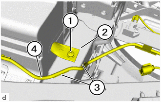
Install the radiator brace rod sub-assembly (2) with T50 bolt (1).
- Torque:
- 19 N*m (194 kgf*cm, 14 ft.*lbf)
- HINT:
-
Perform the operations on the left and right side.
Engage the clamps (3) to connect the No. 4 engine room wire (4).
- HINT:
-
Perform the operations on the left and right side.
52146J
21.INSTALL LOWER AUXILIARY COOLANT RADIATOR BRACKET LH
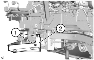
Install the lower auxiliary coolant radiator bracket LH (2) with the T45 bolts (1).
- Torque:
- 19 N*m (194 kgf*cm, 14 ft.*lbf)
52145J
22.INSTALL LOWER AUXILIARY COOLANT RADIATOR BRACKET RH
- HINT:
-
Use the same procedure as for the LH side.
52144L
23.INSTALL UPPER AUXILIARY COOLANT RADIATOR BRACKET LH
- HINT:
-
Description is for left component only. Procedure on the right side is identical.
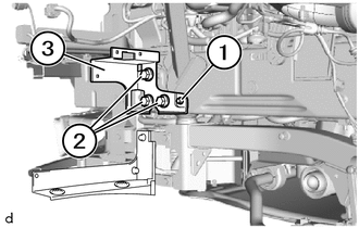
Install the upper auxiliary coolant radiator bracket LH (3) with the T45 bolt (1).
- Torque:
- 19 N*m (194 kgf*cm, 14 ft.*lbf)
Using a deep socket wrench 18 mm, install the replace 18 mm bolts (2).
- Torque:
- 100 N*m (1020 kgf*cm, 74 ft.*lbf)
52143J
24.INSTALL UPPER AUXILIARY COOLANT RADIATOR BRACKET RH
- HINT:
-
Description is for left component only. Procedure on the right side is identical.
25.INSTALL SUB RADIATOR AIR DUCT LH (for B58)
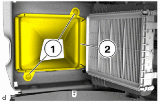
Install the sub radiator air duct LH (2) with clips (1).
26.INSTALL SUB RADIATOR AIR DUCT RH (for B58)
- HINT:
-
Use the same procedure as for the LH side.
27.INSTALL SUB RADIATOR SUPPORT (for LH Side)
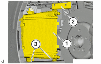
Install the sub radiator support (3).
Connect the sub radiator LH (1) to install the auxiliary coolant radiator bracket plate LH (2).
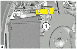
Install the T45 bolts (1).
- Torque:
- 19 N*m (194 kgf*cm, 14 ft.*lbf)
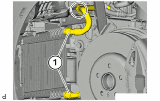
Engage the clip in the marked area.
28.INSTALL SUB RADIATOR SUPPORT (for RH Side)
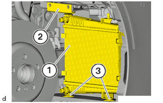
Install the sub radiator support (3).
Connect the sub radiator RH (1) to install the auxiliary coolant radiator bracket plate RH (2).
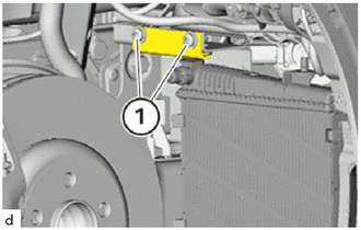
Install the T45 bolts (1).
- Torque:
- 19 N*m (194 kgf*cm, 14 ft.*lbf)
57161
29.INSTALL FRONT CROSSMEMBER
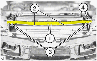
Install the front crossmember (4) with bolts (3).
- Torque:
- 19 N*m (194 kgf*cm, 14 ft.*lbf)
Install the T50 bolts (1) and T30 bolts (2).
- Torque:
- 19 N*m (194 kgf*cm, 14 ft.*lbf)
53295A
30.INSTALL RADIATOR UPPER AIR DEFLECTOR
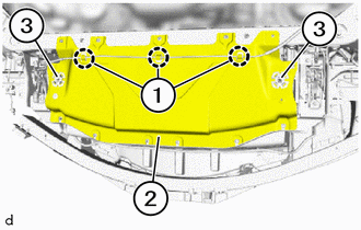
Engage the guides (3) to install the radiator upper air deflector (2).
Connect the hood lock control cable assembly on the guides(1).
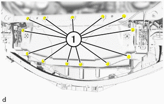
Install the bolts (1).
- Torque:
- 19 N*m (194 kgf*cm, 14 ft.*lbf)
52521B
31.INSTALL FRONT BUMPER UPPER RETAINER
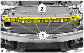
Install the front bumper upper retainer (2) with bolts (1).
- Torque:
- : 8.0 N*m (82 kgf*cm, 71 in.*lbf)
53111M
32.INSTALL FRONT BUMPER INNER SUPPORT
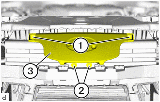
Install the front bumper inner support (3) with T30 bolts (1) and bolts (2).
- Torque:
- Bolt (1) : 4.0 N*m (41 kgf*cm, 35 in.*lbf)
- Bolt (2) : 2.6 N*m (27 kgf*cm, 23 in.*lbf)
52611
33.INSTALL FRONT BUMPER ENERGY ABSORBER
w/o Pedestrian detection chamber assembly:
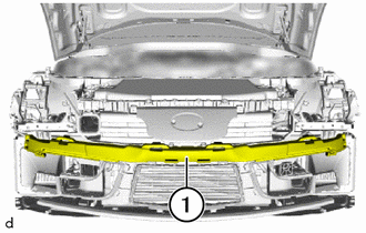
Replace the front bumper energy absorber(1).
Install the front bumper energy absorber (1).
w/ Pedestrian detection chamber assembly:
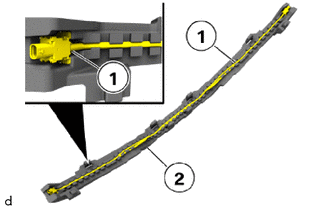
Replace the front bumper energy absorber (1).
Carefully install the pedestrian detection chamber assembly (1) into the front bumper energy absorber (2).
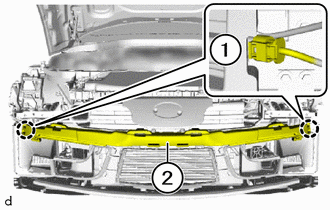
Install the front bumper energy absorber with pedestrian detection chamber assembly (2).
Connect the connectors (1).
86510D
34.INSTALL HIGH PITCHED HORN ASSEMBLY
Click hereVehicle Exterior>HORN>HORN>INSTALLATION
86510C
35.INSTALL HIGH PITCHED HORN ASSEMBLY (for Dual Type)
- HINT:
-
Use the same procedure as for the opposite side.
81150
36.INSTALL HEADLIGHT ASSEMBLY LH
81110
37.INSTALL HEADLIGHT ASSEMBLY RH
- HINT:
-
Use the same procedure as for the LH side.
53896B
38.INSTALL FRONT FENDER FRONT SPLASH SHIELD LH
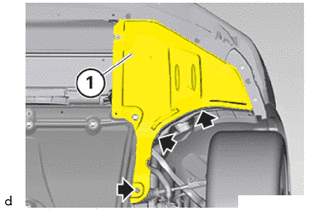
Install the front fender front splash shield LH (1) with screws (arrows).
- Torque:
- 2.6 N*m (27 kgf*cm, 23 in.*lbf)
53895B
39.INSTALL FRONT FENDER FRONT SPLASH SHIELD RH
- HINT:
-
Use the same procedure as for the LH side.
51410
40.INSTALL NO. 1 ENGINE UNDER COVER ASSEMBLY
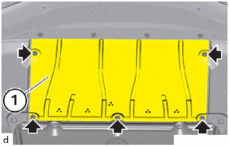
Install the No. 1 engine under cover assembly (1) with screws (arrows).
- Torque:
- 3.0 N*m (31 kgf*cm, 27 in.*lbf)
89348
41.INSTALL NO. 1 ULTRASONIC SENSOR RETAINER
52829C
42.INSTALL COOL AIR INTAKE GRILLE LH
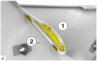
Engage the claws (2) to install the cool air intake grille LH (1).
52829B
43.INSTALL COOL AIR INTAKE GRILLE RH
- HINT:
-
Use the same procedure as for the LH side.
44.INSTALL NUT
- HINT:
-
Perform the following procedure only when replacement of a nut.
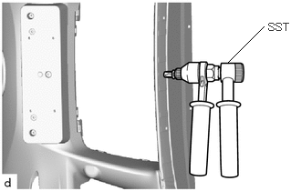
Using SST, install 3 new nuts.
- SST
- 09000-WA040
76081
45.INSTALL FRONT SPOILER SUB-ASSEMBLY
When install a new front spoiler sub-assembly, drill holes in the front spoiler sub-assembly.
Printout the pattern shown in the illustration to a printer at the same size, and cut pattern A, pattern B, and pattern C.
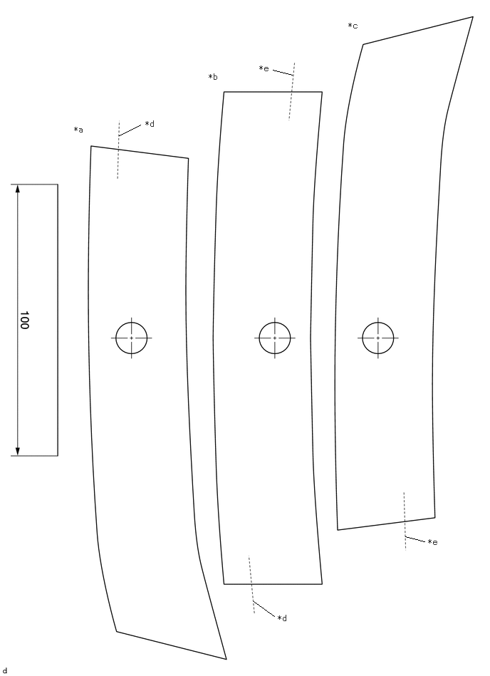
| *a | Pattern A | *b | Pattern B |
| *c | Pattern C | *d | Reference Line A |
| *e | Reference Line B | - | - |
Using a tape, align the reference line A and the reference line B, and attach the pattern A, pattern B, and pattern C.
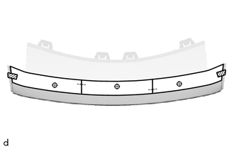

|
Tape |
Using a tape, fix the pattern to the front spoiler sub-assembly as shown in the illustration.
Insert a 11.5 mm (0.453 in.) drill bit into a drill.
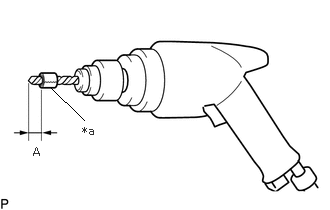
| *a | Tape |
Tape the 11.5 mm (0.453 in.) drill bit 5.0 mm (0.197 in.) from the tip as shown in the illustration.
- Standard Measurement:
Area Measurement A 5.0 mm (0.197 in.)
- NOTICE:
-
Tape the 11.5 mm (0.453 in.) drill bit to prevent the drill bit from going too deep.
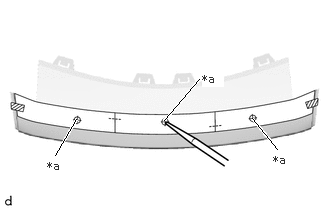
| *a | Reference Point |
Using a center punch, strike 3 punch marks for drilling in the reference point.
Remove the pattern.
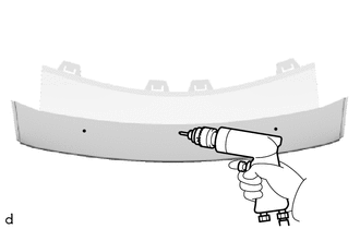
Using a drill, drill 3 holes in the front spoiler sub-assembly.
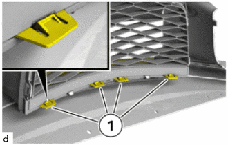
Engage the claws (1) to install the front spoiler sub-assembly.
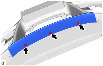
Install the 3 T30 bolts.
76083B
46.INSTALL FRONT SIDE SPOILER LH
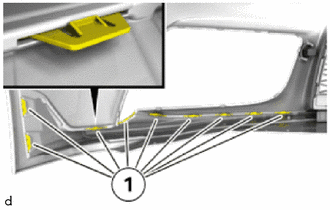
Engage the claws (1) to install the front side spoiler LH.
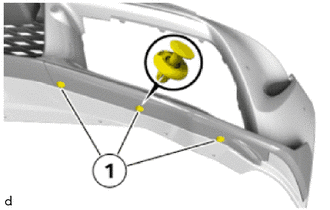
Install the clips (1).
76081C
47.INSTALL FRONT SIDE SPOILER RH
- HINT:
-
Use the same procedure as for the LH side.
52536
48.INSTALL FRONT BUMPER SIDE RETAINER LH
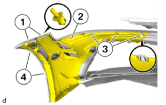
Engage the guides (4) to install the front bumper side retainer LH (2).
Engage the claws (3).
Install the clips (1).
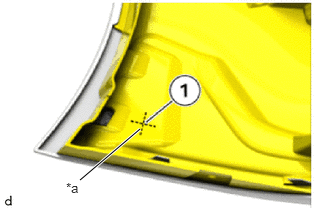
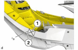
| *a | Scribed Line |
In central point (1) of the crack lines, drill a 6.0 mm (0.236 in.) bore hole for plastic rivet.
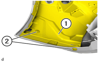
| *a | Scribed Line |
Determine the central point (1) between the crack lines (2).
In the area (1) drill out a 6.0 mm (0.236 in.) bore hole for plastic rivet.
Install the front bumper side retainer LH (1) with plastic rivets (2).
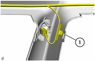
Engage the clamp (1).
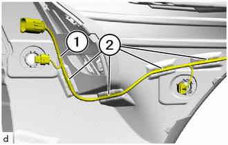
Engage the clamps (2) to connect the No. 4 engine room wire (1).
52535
49.INSTALL FRONT BUMPER SIDE RETAINER RH
- HINT:
-
Use the same procedure as for the LH side.
52127C
50.INSTALL FRONT BUMPER HOLE COVER
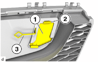
Engage the hook (3).
Engage the claw (2) to install the front bumper hole cover (1).
53113D
51.INSTALL LOWER RADIATOR GRILLE LH
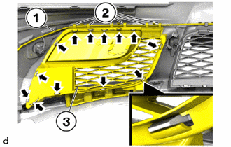
Engage the claws (arrows) to install the lower radiator grille LH (3).
Engage the No. 4 engine room wire (1) to the holder (2) on the lower radiator grille LH (3).
52.INSTALL MILLIMETER WAVE RADAR SENSOR (w/ Toyota Supra Safety)
53127D
53.INSTALL LOWER SIDE RADIATOR GRILLE RH
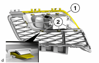
Engage the claws (2) to install the lower side radiator grille RH (1).
53112D
54.INSTALL LOWER RADIATOR GRILLE RH
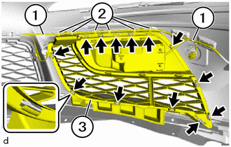
Engage the claws (arrows) to install the lower radiator grille RH (3).
Connect the No. 4 engine room wire (1) to the holders (2) on the lower radiator grille RH (3).
w/ Toyota Supra Safety:
Connect the connector.
53112E
55.INSTALL LOWER NO. 1 RADIATOR GRILLE
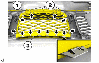
Engage the claws (arrows) to install the lower No. 1 radiator grille (3).
Connect the No. 4 engine room wire (1) to the holders (2) on the lower No. 1 radiator grille (3).
89341M
56.INSTALL FRONT SIDE ULTRASONIC SENSOR
89341K
57.INSTALL FRONT CORNER ULTRASONIC SENSOR
89341L
58.INSTALL FRONT CENTER ULTRASONIC SENSOR
- HINT:
-
Use the same procedure as for the front corner ultrasonic sensor.
75301A
59.INSTALL FRONT BUMPER EMBLEM SUB-ASSEMBLY
52114A
60.INSTALL FRONT BUMPER EXTENSION MOUNTING BRACKET
- NOTICE:
- ·
Malfunction of the ultrasonic sensor.
Incorrect assembly of the license plate leads to a malfunction of the ultrasonic sensor.
-Fix license plate and front bumper extension mounting bracket only according to the dimensions specified in the repair instructions.
-Only use front bumper extension mounting bracket that have been approved for the vehicle type.
-The license plate carrier must not be installed on the front bumper.
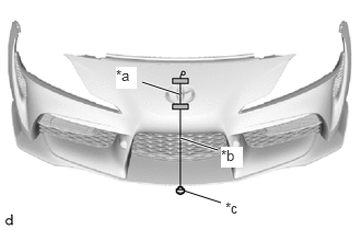
| *a | Center of The Front Bumper Emblem Sub-assembly |
| *b | String |
| *c | Weight |

|
Tape |
Hang the weight from the center of the front bumper emblem sub-assembly as shown in the illustration.
- HINT:
-
Lightly flick the string with your fingers several times to confirm that the string is perpendicular to the ground.
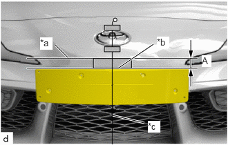
| *a | Bumper Panel Edge |
| *b | Lower Edge of The Tape And Upper Edge of The Front Bumper Extension Mounting Bracket |
| *c | String |
|
|
Tape |
Set the front bumper extension mounting bracket on the front bumper assembly as shown in the illustration.
- Standard (except Korea):
Area Specified Condition A 37 mm (1.46 in.)
- Standard (for Korea):
Area Specified Condition A 16.5 mm (0.650 in.)
- HINT:
-
Match the lower edge of the tape with the upper edge of the front bumper extension mounting bracket.
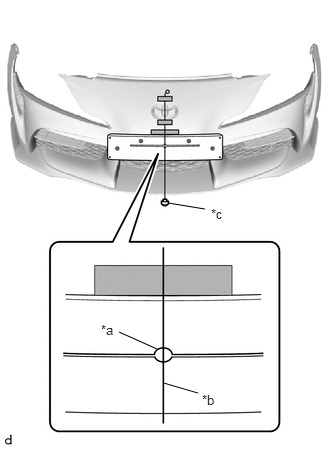
| *a | Center of Front Bumper Extension Mounting Bracket |
| *b | String |
| *c | Weight |
|
|
Tape |
Make sure that the center of the bumper extension mounting bracket and the center of the front bumper emblem sub-assembly match.
Make sure that the dimple of the bumper extension mounting bracket and the distance between the front bumper are even.
- HINT:
-
Perform the operations on the left and right side.
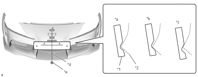
| *1 | Bumper Extension Mounting Bracket | *2 | Front Bumper Assembly |
| *a | Even | *b | Too high |
| *c | Too low | *d | String |
| *e | Weight | - | - |
|
|
Tape | - | - |
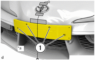
| *a | String |
|
|
Tape |
Install screws (1) the front bumper extension mounting bracket without pre-drilling.
Remove the tape, string and weight.
61.INSTALL FASTENER
for Front Bumper Assembly Side:
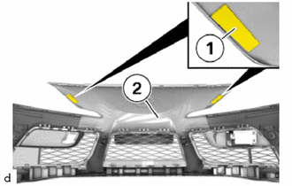
Install the fasteners (1) to the front bumper assembly (2) as shown in the illustration.
for Vehicle Body Side:
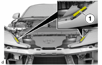
Install the fasteners (1) as shown in the illustration.