B48 ENGINE MECHANICAL CAMSHAFT REMOVAL
PROCEDURE

 13050
1.REMOVE CAMSHAFT TIMING GEAR ASSEMBLY
13070A
2.REMOVE CAMSHAFT TIMING EXHAUST GEAR ASSEMBLY
3.INSPECT AND ADJUST CAMSHAFT
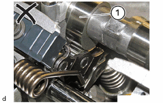
Check position of the intake camshaft sub-assembly on the respective cylinders.
Cam (1) of the intake camshaft sub-assembly runs on the intermediate lever.
Continue to crank the intake camshaft sub-assembly on the mounting flats.
4.REMOVE TORSION SPRING
- CAUTION:
- ·
Spring preload.
Danger of injury!
-The use of the specified special tool (tool) is mandatory.
-The described operation must be carried out properly.
- HINT:
-
Wear safety goggles.
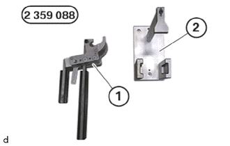
Have the set of special tools 2 359 088 ready.
- SST
- 09200-WA410
| Number | Description |
|---|---|
| 1 | Clamping lever |
| 2 | Mounting for the clamping lever (fitting aid) |
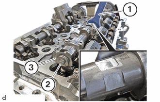
Secure the intake camshaft sub-assembly with a conventional open-end spanner (1).
Loosen bolt (2).
Thread out camshaft sensor wheel (3) and remove.
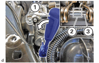
Position standard hexagon socket wrench of 4 mm (1) on the servo motor.
Using the servo motor adjust the No. 3 camshaft sub-assembly (3) slowly in the direction of arrow to minimum lift.
Make sure that the mark (2) on the No. 3 camshaft sub-assembly (3) points upwards.
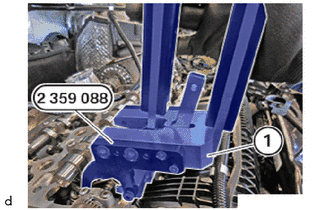
Thread in clamping lever (1) of special tool 2 359 088 and position it.
- SST
- 09200-WA410
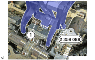
Make sure that the torsion spring (1) in the special tool 2 359 088 is correctly positioned.
- SST
- 09200-WA410
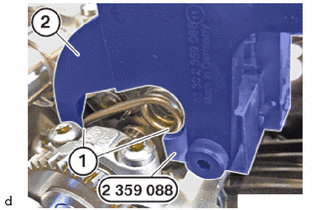
Make sure that the torsion spring (1) is correctly positioned in the clamping lever (2) of the special tool 2 359 088.
- SST
- 09200-WA410
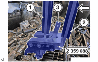
Make sure that the special tool is fitted flat in the area of the cylinder head sub-assembly.
Hold down lever (1) of special tool 2 359 088.
- SST
- 09200-WA410
Close lever (2) of the special tool 2 359 088 carefully in the direction of arrow until the retaining hook (3) engages audibly.
- SST
- 09200-WA410
Thread out clamping lever (1) of special tool 2 359 088 with pre-tensioned torsion spring carefully then remove.
- SST
- 09200-WA410
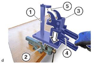
Clamp fixture (1) of the special tool 2 359 088 in the vice (2).
- SST
- 09200-WA410
Position clamping lever (3) of special tool 2 359 088 with pre-tensioned torsion spring (5) in direction of arrow in the mounting (1) of the special tool 2 359 088.
- SST
- 09200-WA410
Carefully unlock retaining hook (4) of the special tool 2 359 088.
- SST
- 09200-WA410
The torsion spring (5) is relieved.
Slowly open clamping lever (3) and remove the torsion spring (5).
Repeat the operations for the remaining torsion spring.
13908A
5.REMOVE GATE
13800
6.REMOVE INTERMEDIATE LEVER
7.REMOVE SST
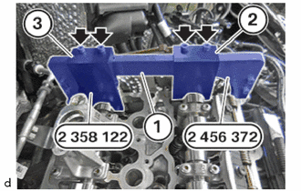
Remove bolts (arrows).
Guide the test gauge (2) out of the set of special tools 2 358 122 between the intake camshaft sub-assembly and the basic carrier (1) of the set of special tools 2 456 372 and remove.
- SST
- 09200-WA380
09200-WA700
Guide the test gauge (3) out of the set of special tools 2 358 122 between the exhaust camshaft sub-assembly and the basic carrier (1) of the set of special tools 2 456 372 and remove.
- SST
- 09200-WA380
09200-WA700
13501A
8.REMOVE INTAKE CAMSHAFT SUB-ASSEMBLY
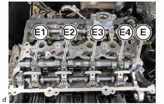
Observe the numbering of the camshaft bearing caps.
The camshaft bearing caps are numbered from (E1) to (E4).
The camshaft bearing caps can be read from the intake side.
The camshaft bearing cap (E) is a thrust bearing.
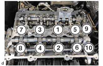
Loosen all T30 bolts on the camshaft bearing caps in sequence from (10) to (1).
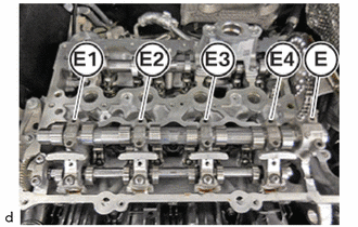
Remove the camshaft bearing caps (E1), (E2),(E3), (E4), (E).
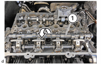
Guide out the intake camshaft sub-assembly (1) in the direction of arrow and remove it.
13502B
9.REMOVE EXHAUST CAMSHAFT SUB-ASSEMBLY
- NOTICE:
- ·
Contaminant or foreign body.
Contamination can result in malfunctions, operating failure or leaks.
-Adhere to the utmost cleanliness.
-Protect components from contamination e.g. by covering.
-Close off line connections with seal plugs.
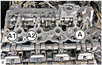
Observe the numbering of the exhaust camshaft bearing caps.
The exhaust camshaft bearing caps are numbered from (A1) to (A2).
The exhaust camshaft bearing caps can be read from the intake side.
The exhaust camshaft bearing cap (A) is a thrust bearing.
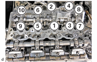
Loosen all T30 bolts on the exhaust camshaft bearing cap in sequence from (10) to (1) in half turn.
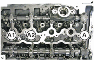
Remove exhaust camshaft bearing caps (A1), (A2) and (A).
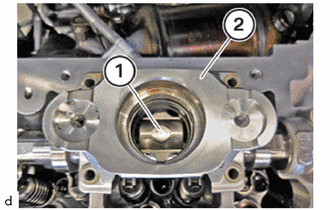
Thread the roller tappet (1) out and remove.
Thread the exhaust camshaft bearing cap (2) out and remove.
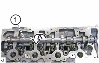
Guide the exhaust camshaft sub-assembly (1) out in the direction of the arrow and remove.