B58 ENGINE MECHANICAL CAMSHAFT INSTALLATION
PROCEDURE

 13502B
1.INSTALL EXHAUST CAMSHAFT SUB-ASSEMBLY
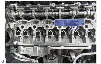
Clean all bearing positions (arrows) and coat with engine oil.
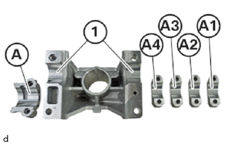
Clean all bearing positions of exhaust camshaft bearing caps (A1), (A2), (A3), (A4) and (A) and coat with engine oil.
Clean bearing positions (1) of the exhaust camshaft bearing cap and coat with engine oil.
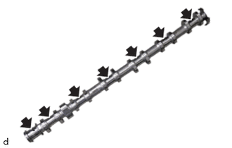
Clean all bearing positions (arrows) of the exhaust camshaft sub-assembly and coat with engine oil.
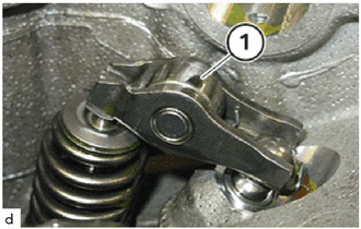
Check all No. 1 valve rocker arm sub-assembly (1) of the exhaust side for correct fit.
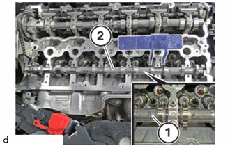
Insert exhaust camshaft sub-assembly (2) in the cylinder head sub-assembly, such that the mark (1) points upwards.
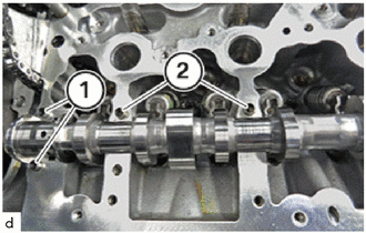
Check the ring pins (1) of the thrust bearing for damage and replace if necessary.
Check the ring pins (2) of the exhaust camshaft bearing cap for damage and replace if necessary.
- NOTICE:
- ·
Engine damage caused by incorrectly installed bearing shells and bearing supports.
Engine damage may result from incorrectly installing bearing shells and bearing supports.
-Always install all bearing shells and bearing supports in the same position from which they were removed.
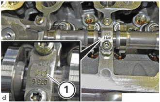
Replace all exhaust camshaft bearing caps, so that the labelling (1) from the intake side is readable.
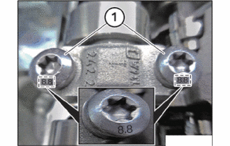
Check the tensile strength of the screws for the bearing caps.The figure shows the screw with the tensile strength of 8,8.
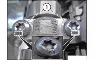
Check the tensile strength of the screws for the bearing caps.The figure shows the screw with the tensile strength of 10,9.
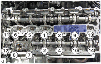
Press down the exhaust camshaft bearing caps and hand-tighten the T30 bolts incrementally in the sequence (1) to (14).
Move up all T30 bolts in the sequence (1) to (14) in half rotations.
Adhere to the jointing torque.
Tighten all T30 bolts in sequence (1) to (14).
- Torque:
- Tensile strength of screw 8.8 : 9.6 N*m (98 kgf*cm, 85 in.*lbf)
- Tensile strength of screw 10.9 : 11.8 N*m (120 kgf*cm, 9 ft.*lbf)
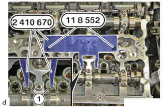
Release special tool 2 410 670 using the spindle nut.
- SST
- 09200-WA500
Release special tool 0 495 741 (11 8 552) and remove special tool 2 410 670 .
- SST
- 09200-WA500
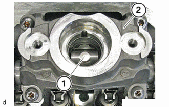
Install fuel pump lifter assembly (1) into the exhaust camshaft bearing cap (2).
13501A
2.INSTALL INTAKE CAMSHAFT SUB-ASSEMBLY
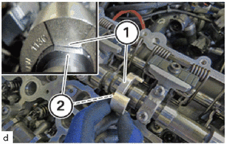
Feed in and position camshaft sensor wheel (1) on the intake camshaft sub-assembly (2).
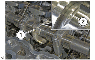
Rotate intake camshaft sub-assembly, if necessary in the position shown.
The recess (2) must point upwards.
Using 3 mm hexagon wrench, Tighten down bolt (1).
- Torque:
- 4.5 N*m (46 kgf*cm, 40 in.*lbf)
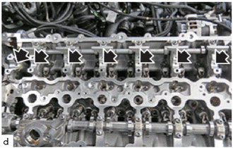
Clean all bearing positions (arrows) and coat with engine oil.
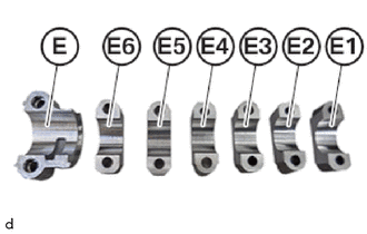
Clean all bearing positions of camshaft bearing caps (E1), (E2), (E3), (E4), (E5), (E6) and (E) and coat with engine oil.
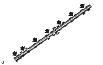
Clean all bearing positions (arrows) of the intake camshaft sub-assembly and coat with engine oil.
Check all roller cam followers(1) of the intake side for correct fit.
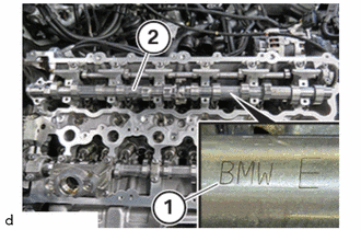
Insert the intake camshaft sub-assembly (2) into the cylinder head sub-assembly so that the mark (1) points up.
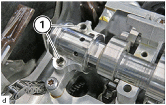
Check the ring pins (1) of the thrust bearing for damage and replace if necessary.
- NOTICE:
- ·
Engine damage caused by incorrectly installed bearing shells and bearing supports.
Engine damage may result from incorrectly installing bearing shells and bearing supports.
-Always install all bearing shells and bearing supports in the same position from which they were removed.
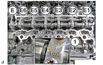
Pull in all camshaft bearing caps (E1) to (E6) and the intake camshaft sub-assembly bearing cap (E) and position.
Check the tensile strength of the screws for the bearing caps.The figure shows the screw with the tensile strength of 8,8.
Check the tensile strength of the screws for the bearing caps.The figure shows the screw with the tensile strength of 10,9.
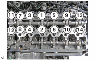
Press down the camshaft bearing caps and hand-tighten the T30 bolts incrementally in the sequence (1) to (14).
Move up all T30 bolts in the sequence (1) to (14) in half rotations.
Adhere to the jointing torque.
Tighten all T30 bolts in sequence (1) to (14).
- Torque:
- Tensile strength of screw 8.8 : 9.6 N*m (98 kgf*cm, 85 in.*lbf)
- Tensile strength of screw 10.9 : 11.8 N*m (120 kgf*cm, 9 ft.*lbf)
3.ADJUST CAMSHAFT
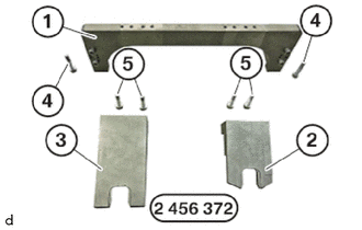
Have the set of special tools 2 456 372 ready.
- SST
- 09200-WA700
| Number | Description |
| 1 | Basic carrier |
| 2 | 0.7° setting gauge to adjust the intake camshaft sub-assembly |
| 3 | 0.5° setting gauge to adjust the exhaust camshaft sub-assembly |
| 4 | Basic carrier bolts on cylinder head |
| 5 | Bolt gauge on basic carrier |
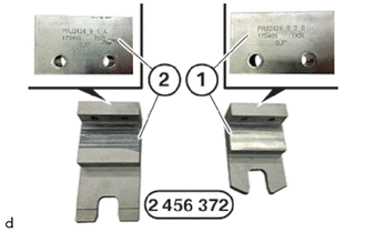
Use the setting gauge 0.7 ° (1) from the set of special tools 2 456 372 to adjust the intake camshaft sub-assembly.
- SST
- 09200-WA700
Use the setting gauge 0.5 ° (2) from the set of special tools 2 456 372 to adjust the exhaust camshaft sub-assembly.
- SST
- 09200-WA700
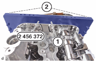
Position the basic carrier (1) from the set of special tools 2 456 372 on the cylinder head sub-assembly.
- SST
- 09200-WA700
Tighten the bolts (2) from the set of special tools 2 456 372 .
- SST
- 09200-WA700
- Torque:
- 8.0 N*m (82 kgf*cm, 71 in.*lbf)
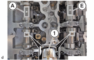
Turn the intake camshaft sub-assembly (E) and the exhaust camshaft sub-assembly (A) until the marks (1) can be read from the top.
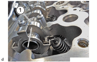
Ensure that the cam (1) on the exhaust camshaft sub-assembly on cylinder 1 points to the inside right at a slight angle.
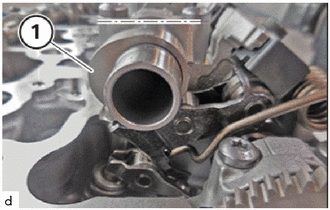
Ensure that the cam (1) on the intake camshaft sub-assembly on cylinder 1 points to the inside left at an angle.
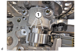
Ensure that the flattened areas (1) on the intake camshaft sub-assembly and the exhaust camshaft sub-assembly point upwards.
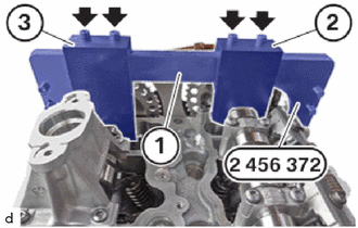
Position the setting gauge 0.5 ° (3) from the set of special tools 2 456 372 between the exhaust camshaft sub-assembly and the basic carrier (1) from the set of special tools 2 456 372 .
- SST
- 09200-WA700
Position the 0.7 setting gauge (2) from the set of special tools 2 456 372 between the intake camshaft sub-assembly and the basic carrier (1) from the set of special tools 2 456 372 .
- SST
- 09200-WA700
Tighten bolts (arrows).
- Torque:
- 8.0 N*m (82 kgf*cm, 71 in.*lbf)
13800
4.INSPECT INTERMEDIATE LEVER
13800
5.INSTALL INTERMEDIATE LEVER
13908A
6.INSTALL GATE
7.INSTALL TORSION SPRING
13050
8.INSTALL CAMSHAFT TIMING GEAR ASSEMBLY
13070A
9.INSTALL CAMSHAFT TIMING EXHAUST GEAR ASSEMBLY