B58 ENGINE MECHANICAL ENGINE WIRE HARNESS(for No. 1) INSTALLATION
PROCEDURE

 82121
1.INSTALL ENGINE WIRE
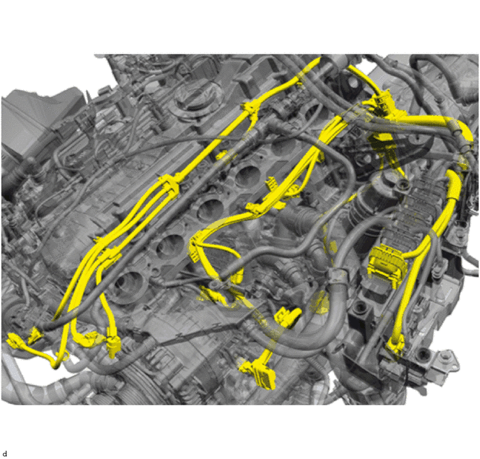
- NOTICE:
- ·
Improper routing of cables and wiring harnesses.
Trapped, crushed or damaged cables may cause short circuits and malfunctions.
-Route all cables without abrasions, do not trap and crush.
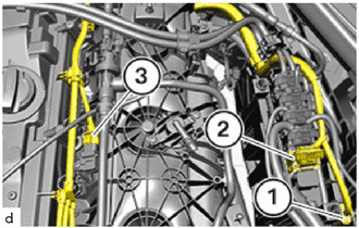
Thread in and install the engine wire.
Secure all clamps
Route the connector (1) to the No. 1 integration relay.
Route the connector (2) to the ECM.
Connect and lock the connector (3) of the vacuum sensor assembly.
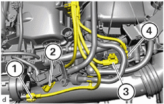
Connect and lock the connector (1) of the water pump assembly (for Turbo).
Connect and lock the connector (2) of the No. 2 engine wire.
Connect and lock the connector (3) of the air pressure sensor.
Connect and lock the connector (4) for the inlet air temperature sensor.
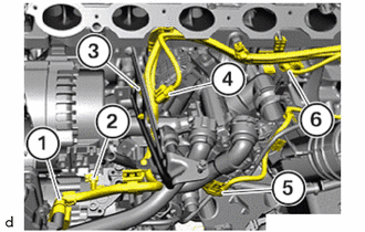
Connect and lock the connector (1) for the throttle body with motor assembly.
Connect and lock the connector (2) for the generator assembly.
Connect and lock the connector (3) of the knock sensor of cylinders 1 to 3.
Connect and lock the connector (4) for the water valve with bracket assembly.
Connect and lock the lower connector (5) of the water valve with bracket assembly.
Connect and lock the connector (6) of the knock sensor of cylinders 4 to 6.
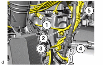
Connect and lock the connector (1) of the oil temperature sensor.
Connect and lock the connector (2) for the oil pressure sensor.
Connect and lock the connector (3) of the oil pressure control valve assembly.
Connect and lock the connector (4) for the crankshaft position sensor.
Tighten the T30 bolts (5).
- Torque:
- 8.0 N*m (82 kgf*cm, 71 in.*lbf)
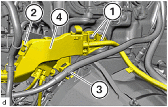
Mount cable channel (4).
Tighten the E8 bolts (1).
- Torque:
- 8.0 N*m (82 kgf*cm, 71 in.*lbf)
Lock clamp (2).
Secure positive battery cable at the clamp (3).
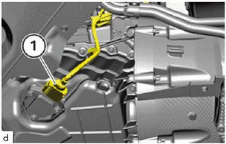
Connect and lock the connector (1) of the engine oil level sensor.
17111
2.INSTALL INTAKE MANIFOLD
12140
3.INSTALL OIL PAN COVER
51219
4.INSTALL FRONT SUSPENSION MEMBER LOWER PROTECTOR