B58 INTAKE / EXHAUST INTAKE MANIFOLD INSTALLATION
PROCEDURE

 17111
1.INSTALL INTAKE MANIFOLD
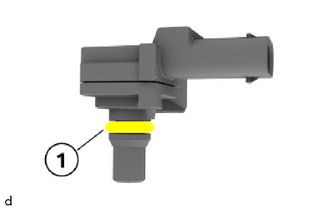
Check the sealing ring for damage and replace where required.
Apply a thin coat of syntheso glep 1 lubricating grease to the O-ring (1).
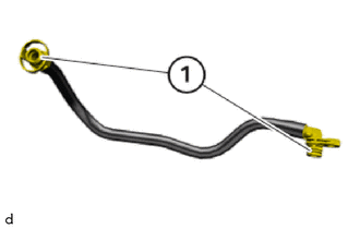
Check sealing rings (1) and replace the No. 3 fuel vapor feed hose where required.
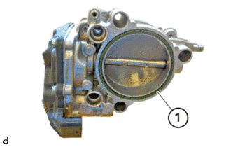
Replace the throttle body gasket (1).
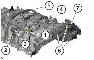
Position the throttle body with motor assembly (7).
Tighten down the bolts (6).
- Torque:
- 7.0 N*m (71 kgf*cm, 62 in.*lbf)
Position the No. 3 fuel vapor feed hose (5).
Tighten down the T20 bolt (4).
- Torque:
- 3.0 N*m (31 kgf*cm, 27 in.*lbf)
Install the vacuum sensor (3).
Tighten down the T25 bolt.
- Torque:
- 4.0 N*m (41 kgf*cm, 35 in.*lbf)
Mount the clip.
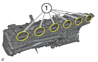
Replace No. 1 intake manifold to head gaskets (1).
Position the intake manifold.
- HINT:
-
Additional coolant can escape. Make sure that no coolant enters the intake port of the cylinder head sub-assembly.
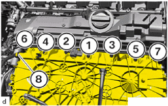
Tighten the bolts in the order to (1) to (7).
- Torque:
- 10 N*m (102 kgf*cm, 7 ft.*lbf)
Connect the fuel suction tube sub-assembly (8) and lock.
- HINT:
- ·
Make sure that the connections are locked correctly. The locks must engage audibly.
·Lock must audibly engage.
Lock the locks and connect the water by-pass hoses.
Tighten the E10 bolts.
- Torque:
- 8.0 N*m (82 kgf*cm, 71 in.*lbf)
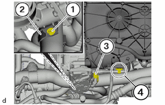
Mount the clip in the marked area (4).
Connect connectors (3) and lock.
Position holder (2).
Tighten down the E10 bolt (1).
- Torque:
- 11.8 N*m (120 kgf*cm, 9 ft.*lbf)
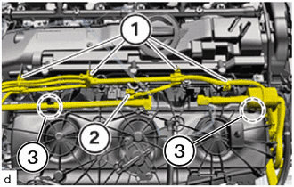
Secure wiring harness (1) on the cylinder head cover sub-assembly.
Connect and lock the connector (2) on the vacuum sensor.
- HINT:
-
Lock must audibly engage.
Secure fuel tank breather tubes on the intake manifold in the marked areas (3).
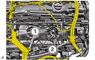
Position wiring harness (1), (2) and fasten on the holders.
- HINT:
-
The locks must engage audibly.
Secure wiring harness (1), (2) in the holder and lock.
2.INSTALL ENGINE ROOM ECU BOX
- NOTICE:
- ·
Improper routing of cables and wiring harnesses.
Trapped, crushed or damaged cables may cause short circuits and malfunctions.
-Route all cables without abrasions, do not trap and crush.
Feed the engine room ECU box into the guide and install.
Tighten down the bolts.
- Torque:
- 8.0 N*m (82 kgf*cm, 71 in.*lbf)
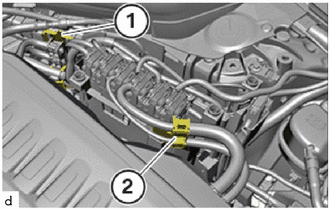
Feed the wiring harnesses (1), (2) into the holder at the engine room ECU box.
- HINT:
-
The locks and must engage audibly.
3.INSTALL NO. 1 INTEGRATION RELAY
23285A
4.INSTALL NO. 1 CHECK VALVE
12611
5.INSTALL NO. 1 ENGINE COVER
55788A
6.INSTALL COWL TOP VENTILATOR LOUVER PROTECTOR
85010
7.INSTALL FRONT WIPER MOTOR AND LINK ASSEMBLY
17882
8.INSTALL NO. 2 AIR CLEANER HOSE
17880
9.INSTALL AIR CLEANER HOSE ASSEMBLY
51219
10.INSTALL FRONT SUSPENSION MEMBER LOWER PROTECTOR
11.CONNECT CABLE TO NEGATIVE BATTERY TERMINAL
12.ADD ENGINE COOLANT (for Low Temperature)
13.INSPECT FOR COOLANT LEAK (for Low Temperature)