B48 ENGINE MECHANICAL FRONT CRANKSHAFT OIL SEAL INSTALLATION
PROCEDURE

 1.INSTALL FRONT CRANKSHAFT OIL SEAL
- NOTICE:
- ·
Front crankshaft oil seal damage.
Touching the sealing lip (inner) and applying oil to the front crankshaft oil seal will lead to its destruction.
-Do not touch the sealing lip (inner) of the front crankshaft oil seal.
-Do not apply oil to the front crankshaft oil seal.
-Install the front crankshaft oil seal dry.
- HINT:
-
The front crankshaft oil seal must be installed dry. Do not use engine oil or lubricant.
Clean the special tool 0 496 128 (11 8 801) from the set of special tools 0 496 127 (11 8 800) and coat it with fresh engine oil.
- SST
- 09200-WA080
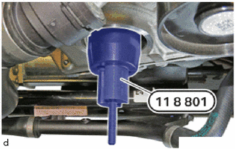
Secure special tool 0 496 128 (11 8 801) to the crankshaft using special tool 0 496 129 (11 8 802).
- SST
- 09200-WA080
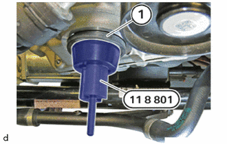
Carefully slide the front crankshaft oil seal (1) in a rotational movement onto the special tool 0 496 128 (11 8 801) until the front crankshaft oil seal rests against the cylinder block sub-assembly.
- SST
- 09200-WA080
The front crankshaft oil seal must not be tilted in the process.
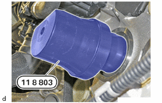
Mount the special tool (sleeve) 0 496 130 (11 8 803) on special tool 0 496 128 (11 8 801).
- SST
- 09200-WA080
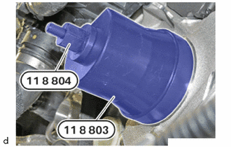
Screw on the special tool (nut) 0 496 131 (11 8 804) until the special tool (sleeve) 0 496 130 (11 8 803) lies flush on the cylinder block sub-assembly.
- SST
- 09200-WA080
This correctly positions the front crankshaft oil seal.
Remove special tools.
13470
2.INSTALL CRANKSHAFT PULLEY ASSEMBLY
- NOTICE:
- ·
Make sure to use SST when installing the crankshaft pulley assembly.
·Performing installation without using SST could result in the crankshaft pulley assembly being off-center, which could damage the crankshaft oil seal.
Apply a small amount of engine oil to the sealing surface of the crankshaft pulley assembly.
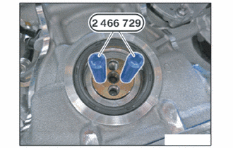
Install SST (2 466 729) to the crankshaft by hand.
- SST
- 09214-WA010
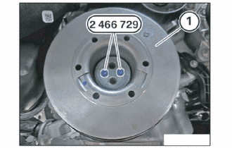
Using SST (2 466 729), temporarily install the crankshaft pulley assembly (1).
- SST
- 09214-WA010
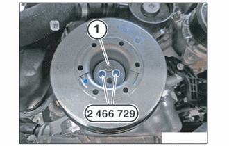
Temporarily install the E12 bolt (1) by hand.
Remove SST (2 466 729).
- SST
- 09214-WA010
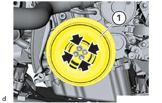
Tighten the E12 bolts (arrows).
- Torque:
- 40 N*m (408 kgf*cm, 30 ft.*lbf)
Using SST, tighten the bolts an additional 120°.
- SST
- 09900-WA010
- HINT:
-
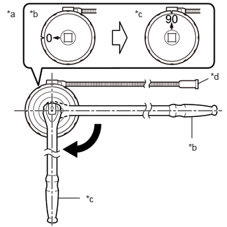 2.99,1.271 3.156,1.188 false 2.906,2.094 2.906,1.76 false 0.875,3 1.208,3 false 0.104,0.125 0.417,0.281 0.313,0.156 10 false *a 0.448,0.125 0.76,0.281 0.313,0.156 10 false *b 2.042,0.125 2.354,0.281 0.313,0.156 10 false *c 3.188,1.073 3.427,1.271 0.24,0.198 10 false *d 2.854,2.146 3.167,2.302 0.313,0.156 10 false *b 1.302,2.927 1.615,3.083 0.313,0.156 10 false *c
*a Example *b Before Tightening *c After Tightening *d Magnetic Portion
- ·
The magnetic portion is used to secure the gauge to the vehicle.
·After first adjusting the needle of the gauge to 0°, tighten to the specified angle.
·Perform the work procedure carefully so that the gauge, etc. does not become tilted.
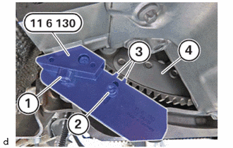
Loosen bolt (2).
Slide the counter support with the bolt (2) back until the teeth (3) are no longer engaged in the gearing of the flywheel sub-assembly (4).
Unscrew the bolt (1) and remove the special tool 0 496 595 (11 6 130).
- SST
- 09700-WA040
28100
3.INSTALL STARTER ASSEMBLY
4.INSTALL FAN AND GENERATOR V BELT
5.CONNECT CABLE FROM NEGATIVE BATTERY TERMINAL