AIRBAG SYSTEM > PRECAUTION |
| 1.HANDLING PRECAUTIONS FOR AIRBAG SENSORS |
Before starting the following operations, wait for at least 90 seconds after disconnecting the negative (-) terminal cable from the battery:
Replacement of the airbag sensors.
Adjustment of the front/rear doors of the vehicle equipped with the side airbag and curtain shield airbag (fitting adjustment).
When connecting or disconnecting the airbag sensor connectors, ensure that each sensor is installed in the vehicle.
Do not use the airbag sensors which has been dropped during the operation or transportation.
Do not disassemble the airbag sensors.
If engine is run immediately after reconnecting negative battery terminal cable, keep it at less than 2000rpm for at least 1 minute.
If the engine exceeds 2,000rpm, the clutch is automatically disengaged by the compressor protection control system.
| 2.INSPECTION PROCEDURE FOR VEHICLE INVOLVED IN ACCIDENT |
When the airbag has not deployed, check for DTCs by checking the SRS warning light blinking patterns or using a intelligent tester. If any DTCs are present, perform troubleshooting for those DTCs.
When any of the airbags have deployed, replace the airbag sensor and check the installation condition.
| 3.SRS CONNECTORS |
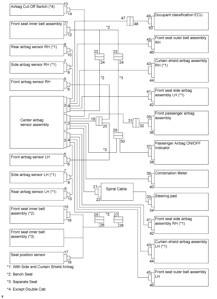
| No. | Connector Type | Application |
| (1) | Terminal Twin-Lock Mechanism | Connectors 2, 4, 6, 8, 10, 19, 20, 21, 23, 24, 31, 41 |
| (2) | Activation Prevention Mechanism | Connectors 2, 4, 22, 32, 42 |
| (3) | Half Connection Prevention Mechanism | Connectors 6, 8, 10, 20, 21, 41 |
| (4) | Connector Lock Mechanism (1) | Connectors 19, 25, 27, 33, 35, 43, 45 |
| (5) | Connector Lock Mechanism (2) | Connectors 2, 4 |
| (6) | Improper Connection Prevention Lock Mechanism | Connectors 1, 3 |
All connectors in the SRS except the seat position sensor connector and the occupant classification ECU connector are colored yellow to distinguish them from other connectors. Some connectors have special functions, and are specially designed for the SRS. These connectors use durable gold-plated terminals, and are placed in the locations shown on the previous page to ensure high reliability.
Terminal twin-lock mechanism:
Each connector has a two-piece component consisting of a housing and a spacer. This design enables the terminal to be locked securely by two locking devices (the retainer and the lance) to prevent the terminals from becoming disconnected.
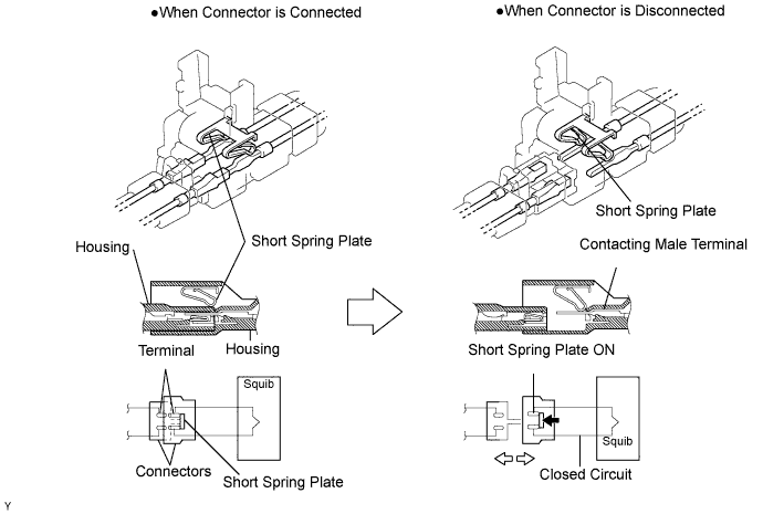
Activation prevention mechanism:
Each connector contains a short spring plate. When the connector is disconnected, the short spring plate automatically connects the positive (+) and negative (-) terminals of the squib.
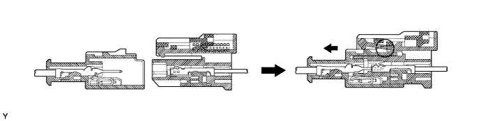
Half connection prevention mechanism:
If the connector is not completely connected, the connector is disconnected due to the spring operation so that no continuity exists.
Connector lock mechanism (1):
Locking the connector lock button connects the connector securely.

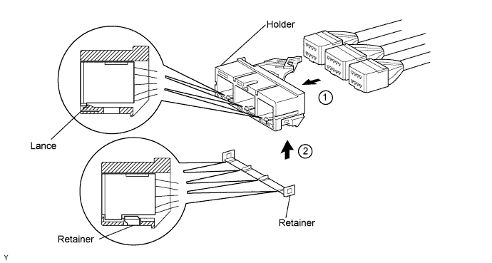
Connector lock mechanism (2):
Both the primary lock with holder lances and the secondary lock with retainer prevent the connectors from becoming disconnected.
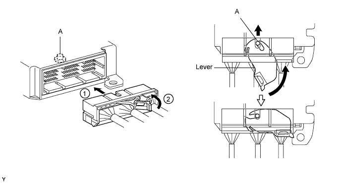
Improper connection prevention lock mechanism:
When connecting the holder, the lever is pushed into the end by rotating around the A axis to lock the holder securely.
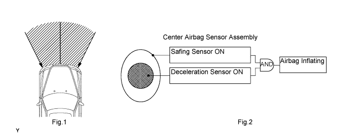
When the vehicle is involved in a frontal collision in the hatched area (Fig.1) and the shock is larger than the predetermined level, the SRS is activated automatically. The safing sensor is designed to activate at a lower deceleration rate than the airbag sensor. As illustrated in Fig.2, ignition is caused when a current flows to the squib, which happens when the safing sensor and the deceleration sensor go on simultaneously. When a deceleration force acts on the sensors, 2 squibs in the driver airbag and front passenger airbag ignite and generate gas. The gas discharging into the driver airbag and front passenger airbag rapidly increases the pressure inside the bags, breaking the Steering pad and instrument panel. The deployment of the bags then ends, and the bags deflate as the gas is discharged through discharge holes at the rear of the bag.
| 4.DISCONNECTION OF CONNECTORS FOR STEERING PAD, FRONT PASSENGER AIRBAG ASSEMBLY AND CURTAIN SHIELD AIRBAG ASSEMBLY |
Release the lock button (yellow part) of the connector using a screwdriver.
Insert the screwdriver tip between the connector and the base, and then raise the connector.
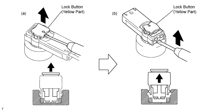
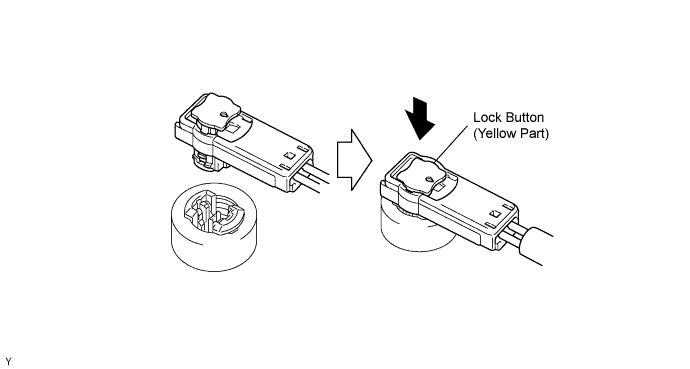
| 5.CONNECTION OF CONNECTORS FOR STEERING PAD, FRONT PASSENGER AIRBAG ASSEMBLY AND CURTAIN SHIELD AIRBAG ASSEMBLY |
Connect the connector.
Push down securely on the lock button (yellow part) of the connector. (When locking, a click sound can be heard.)
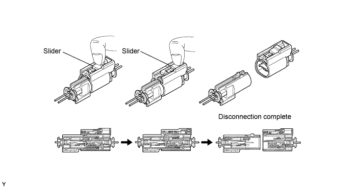
| 6.DISCONNECTION OF CONNECTOR FOR FRONT SEAT SIDE AIRBAG ASSEMBLY |
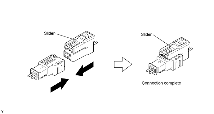
Place a finger on the slider, slide the slider to release the lock, and then disconnect the connector.
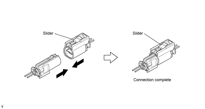
| 7.CONNECTION OF CONNECTOR FOR SEAT SIDE AIRBAG ASSEMBLY |
Connect the connector as shown in the illustration. (When locking, make sure that the slider returns to its original position and a click sound can be heard.)
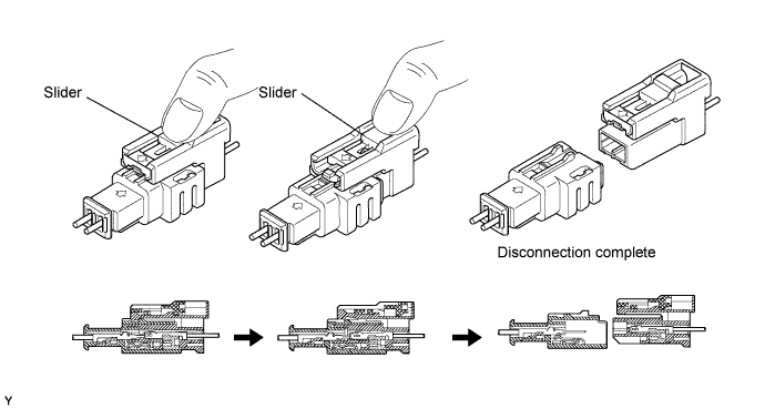
| 8.DISCONNECTION OF CONNECTOR FOR FRONT PASSENGER AIRBAG ASSEMBLY |
Place a finger on the slider, slide the slider to release the lock, and then disconnect the connector.
| 9.CONNECTION OF CONNECTOR FOR FRONT PASSENGER AIRBAG ASSEMBLY |
Connect the connector as shown in the illustration. (When locking, make sure that the slider returns to its original position and a click sound can be heard.)
| 10.DISCONNECTION OF CONNECTOR FOR CENTER AIRBAG SENSOR ASSEMBLY |
Pull the lever by pushing part A as shown in the illustration and disconnect the holder (with connectors).
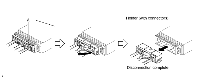
Remove the holder.
Using a screwdriver, unlock the retainer.
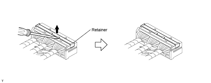
Release the fitting lances and remove the holder.
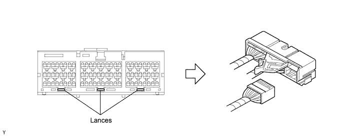
Install the holder.
Install the connectors into the holder. (When locking, a click sound can be heard.)
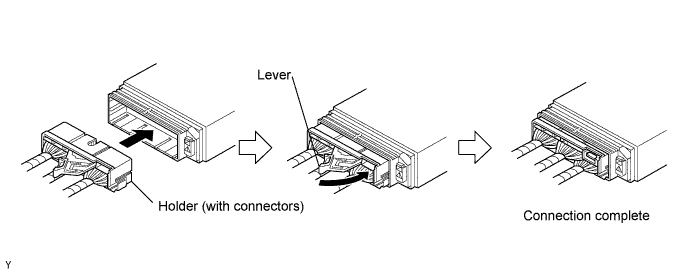
| 11.CONNECTION OF CONNECTOR FOR CENTER AIRBAG SENSOR ASSEMBLY |
Firmly insert the holder (with connectors) until it can not be pushed any further.
Push the lever to connect the holder (with connectors). (When locking, a click sound can be heard.)
| 12.DISCONNECTION OF CONNECTORS FOR FRONT AIRBAG SENSOR, SIDE AIRBAG SENSOR AND REAR AIRBAG SENSOR |
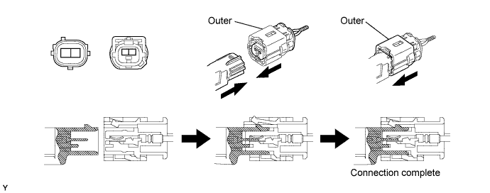
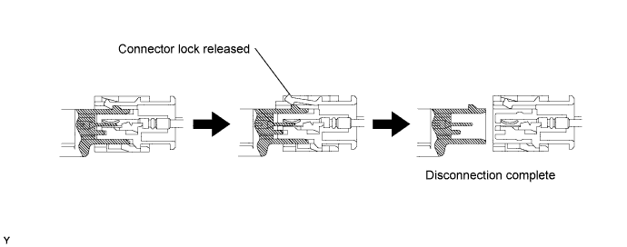
While holding both outer flank sides, slide the outer in the direction shown by the arrow.
When the connector lock is released, the connectors are disconnected.
| 13.CONNECTION OF CONNECTORS FOR FRONT AIRBAG SENSOR, SIDE AIRBAG SENSOR AND REAR AIRBAG SENSOR |
Connect the connector as shown in the illustration. (When locking, make sure that the outer returns to its original position and a click sound can be heard.)