KNOCK SENSOR (for 2WD) > INSTALLATION |
| 1. INSTALL KNOCK SENSOR |
|
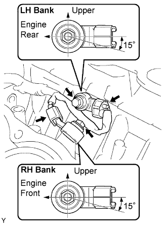
Install the 2 knock sensors with the 2 bolts as shown in the illustration.
Connect the 2 knock sensor connectors.
| 2. INSTALL WATER OUTLET PIPE NO.1 |
Install the water outlet pipe with the 3 bolts.
Install the 4 wire harness clamps.
| 3. CONNECT HEATER WATER INLET HOSE |
| 4. INSPECT CYLINDER HEAD SET BOLT |
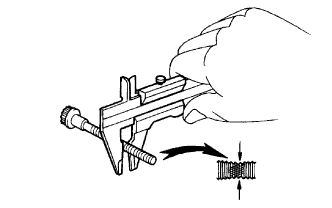 |
Using vernier calipers, measure the outside diameter of the bolt thread.
| 5. INSTALL CYLINDER HEAD SUB-ASSEMBLY |
Place the cylinder head on the cylinder head gasket.
Install the 8 cylinder head bolts.
Apply a light coat of engine oil to the threads of the cylinder head bolts.
Install the plate washer onto the cylinder head bolt.
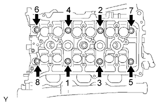 |
Using several steps, tighten each bolt uniformly with a 10 mm bi-hexagon wrench in the sequence shown in the illustration.
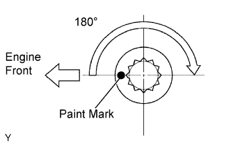 |
Mark the front side of each cylinder head bolt with paint.
Retighten the cylinder head bolts 180° as shown.
Check that the painted marks are now at 180° from the engine front.
Install the ground cables with the 2 bolts.
| 6. INSTALL CAMSHAFT BEARING NO.2 |
| 7. INSTALL CAMSHAFTS |
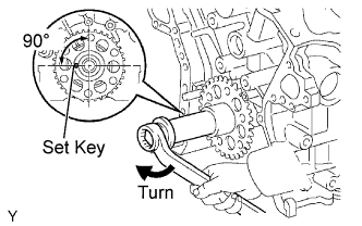 |
Set the crankshaft position.
Using the crankshaft pulley set bolt, turn the crankshaft, and set the crankshaft set key in the left horizontal position.
Apply new engine oil to the thrust portion and journal of the camshafts.
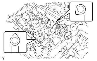 |
Place the 2 camshafts onto the cylinder head with the cam lobes of No. 1 cylinder facing in the directions shown in the illustration.
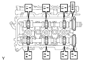 |
Install the 8 bearing caps in the proper locations as shown.
Apply a light coat of engine oil to the threads and under the heads of the bearing cap bolts.
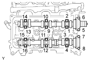 |
Using several steps, uniformly install and tighten the 16 bearing cap bolts in the sequence shown in the illustration.
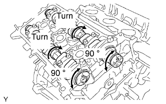 |
Turn the camshafts clockwise until each camshaft knock pin comes to a position 90° to the cylinder head.
| 8. INSTALL CHAIN TENSIONER ASSEMBLY NO.2 |
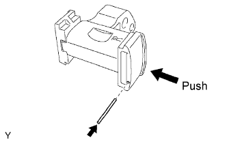 |
While pushing in the tensioner, insert a pin of φ 1.0 mm (0.039 in.) into the hole to fix it.
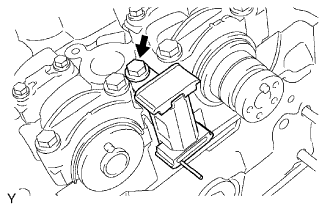 |
Install the chain tensioner No. 2 with the bolt.
| 9. INSTALL CAMSHAFT TIMING GEARS AND NO.2 CHAIN (RH BANK) |
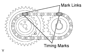 |
Align the yellow mark links with the timing marks (1 dot mark) of camshaft timing gears as shown in the illustration.
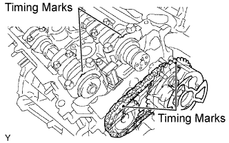 |
Align the timing marks on the camshaft timing gears with the timing marks on the bearing caps, and install the camshaft timing gears with the chain onto the RH camshafts.
Temporarily install the 2 camshaft timing gear bolts.
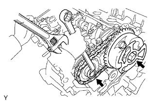 |
Hold the hexagonal portion of the camshaft with a wrench, and tighten the 2 bolts.
Remove the pin from the tensioner No. 2.
| 10. INSTALL CHAIN VIBRATION DAMPER NO.1 |
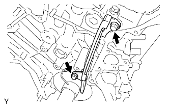 |
Install the chain vibration damper with the 2 bolts.
| 11. INSTALL WATER BY-PASS JOINT RR |
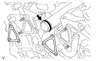 |
Install a new O-ring onto the water outlet pipe.
Apply soapy water to the O-ring.
Install 2 new gaskets and water by-pass joint rear with the 2 bolts and 4 nuts.
Connect the heater hose.
Connect the engine coolant temperature sensor connector.
| 12. INSTALL INTAKE MANIFOLD |
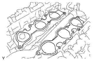 |
Set a new gasket on each cylinder head.
Set the intake manifold on the cylinder heads.
Install and tighten the 10 bolts uniformly in several steps.
Connect the 6 fuel injector connectors.
| 13. INSTALL EXHAUST MANIFOLD SUB-ASSEMBLY RH |
|
Set a new gasket on each cylinder head.
Set the intake manifold on the cylinder heads.
Install and tighten the 10 bolts uniformly in several steps.
Connect the 6 fuel injector connectors.
| 14. INSTALL MANIFOLD STAY |
Install the manifold stay with the 3 bolts.
| 15. INSTALL EXHAUST PIPE ASSEMBLY FRONT |
Install a new gasket onto the exhaust manifold RH.
Install the exhaust front pipe with the new 2 nuts.
| 16. INSTALL EXHAUST FRONT PIPE ASSEMBLY NO.2 |
Install a new gasket onto the exhaust manifold LH.
Install a new gasket onto the exhaust front pipe.
Install the exhaust front pipe No. 2 onto the insulator.
Install the exhaust front pipe No. 2 onto the exhaust manifold LH with the new 2 nuts.
Install the exhaust front pipe No. 2 onto the exhaust front pipe with the 2 bolts and 2 nuts.
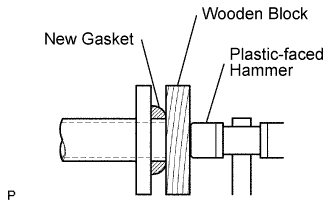 |
Install a new gasket onto the exhaust front pipe No. 2.
Using a wooden block and plastic- faced hammer, tap in a new gasket until it is flush with the exhaust front pipe No. 2.
| 17. INSTALL COOL AIR INLET NO.1 |
Install the cool air inlet with the 2 bolts.
| 18. INSTALL CHAIN TENSIONER SLIPPER |
| 19. INSTALL CHAIN TENSIONER ASSEMBLY NO.1 |
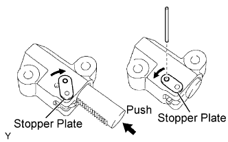 |
While turning the stopper plate of the tensioner clockwise, push in the plunger of the tensioner as shown in the illustration.
While turning the stopper plate of the tensioner counterclockwise, insert a bar of φ 35 mm (0.138 in.) into the holes in the stopper plate and tensioner to fix the stopper plate.
Install the chain tensioner with the 2 bolts.
| 20. INSTALL CHAIN SUB-ASSEMBLY |
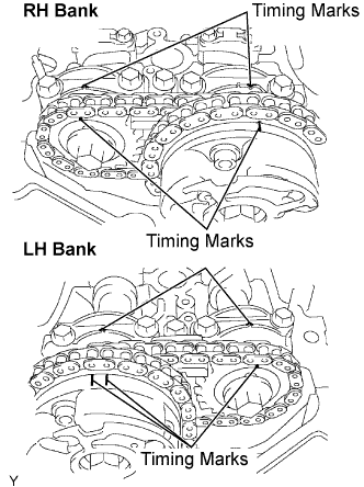 |
Set the No. 1 cylinder to TDC/ compression.
Align the timing marks of the camshaft timing gears and bearing caps.
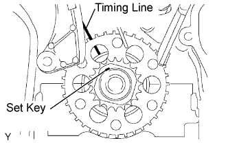 |
Using the crankshaft pulley set bolt, turn the crankshaft to align the crankshaft set key with the timing line of the cylinder block.
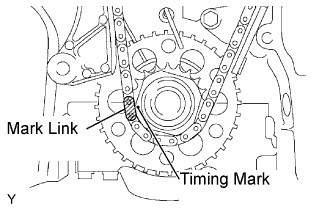 |
Align the yellow mark link with the timing mark of the crankshaft timing link.
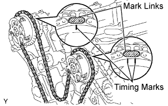 |
Align the orange mark links with the timing marks of the camshaft timing gears, and install the chain.
| 21. INSTALL TIMING CHAIN OR BELT COVER SUB-ASSEMBLY |
| 22. INSTALL ENGINE ASSEMBLY |
| 23. INSTALL BATTERY |
| 24. ADD ENGINE COOLANT |
Pour coolant into the radiator until it overflows.
| Transmission | Capacity |
| Manual Transmission | 9.7 liters (10.3 Us qts, 8.5 Imp. qts) |
| Automatic Transmission | 9.8 liters (10.4 Us qts, 8.6 Imp. qts) |
Check the coolant level inside the radiator by squeezing the inlet and outlet radiator hoses several times by hand. If the coolant level goes down, add coolant.
Install the radiator cap securely.
Slowly pour coolant into the radiator reservoir until it reaches the FULL line.
Warm up the engine until the cooling fan operates.
Set the air conditioning as follows while warming up the engine.
| Item | Condition |
| Fan Speed | Any setting except OFF |
| Temperature | Toward WARM |
| Air Conditioning Switch | OFF |
Maintain the engine speed at 2,000 to 2,500 rpm and warm up the engine until the cooling fan operates.
Squeeze the inlet and outlet radiator hoses several times by hand while warming up the engine.
Stop the engine and wait until the coolant cools down.
Remove the radiator cap and check the coolant level inside the radiator.
If the coolant level is below the full level, perform the steps from (a) through (h) and repeat the operation until the coolant level remains at the full level.
Check the coolant level inside the radiator reservoir tank again. If it is below the full level, add coolant.
| 25. ADD ENGINE OIL |
Fill with fresh engine oil.
| Drain and refill with oil filter change | 4.5 liters (4.8 US qts, 4.0 lmp. qts) |
| Drain and refill without oil filter change | 4.2 liters (4.4 US qts, 3.7 lmp. qts) |
| Dry fill | 5.6 liters (5.9 US qts, 4.9 lmp. qts) |
| Drain and refill with oil filter change | 5.2 liters (5.5 US qts, 4.6 lmp. qts) |
| Drain and refill without oil filter change | 4.9 liters (5.2 US qts, 4.3 lmp. qts) |
| Dry fill | 6.0 liters (6.3 US qts, 5.3 lmp. qts) |
Reinstall the oil filler cap.
| 26. CHECK FOR ENGINE COOLANT LEAKAGE |
Fill the radiator with coolant and attach a radiator cap tester.
Pump it to 118 kPa (1.2 kgf/cm2 17.1 psi), then check for leakage.
| 27. CHECK FOR ENGINE OIL LEAKAGE |
| 28. CHECK FOR FUEL LEAKAGE |
| 29. CHECK FOR EXHAUST GAS LEAKAGE |
| 30. INSPECT IGNITION TIMING |
Warm up the engine.
 |
When using the intelligent tester.
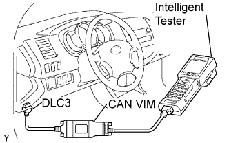
Connect the intelligent tester to the DLC3.
Select the following menu items: DIAGNOSIS / ENHANCED OBD ll / DATA LIST / IGN ADVANCE.
Inspect the ignition timing during idling.
Check that the ignition timing advances immediately when the engine speed is increased.
 |
When not using intelligent tester.
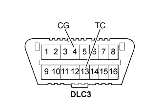
Using SST, connect the terminals 13 (TC) and 4 (CG) of the DLC3.
Remove the air cleaner.
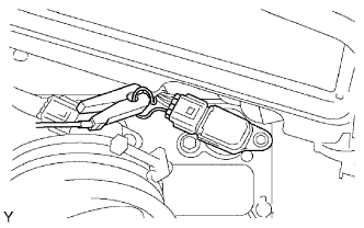 |
Pull out the wire harness as shown in the illustration.
Connect the tester probe of a timing light to the wire of the ignition coil connector for No. 1 cylinder.
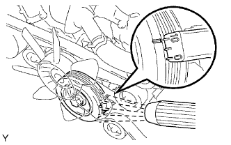 |
Inspect the ignition timing during idling.
Remove the SST from the DLC3.
Inspect the ignition timing during idling.
Install the air cleaner.
| 31. INSPECT ENGINE IDLING SPEED |
Warm up the engine.
|
When using the intelligent tester:
Connect the intelligent tester to the DLC3.
Select the following menu items: DIAGNOSIS / ENHANCED OBD ll / DATA LIST / ENGINE SPD.
Inspect the engine idling speed.
 |
When not using the intelligent tester:
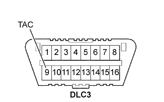
Using SST, connect the terminal 8 (TAC) of the DLC3.
Race the engine speed at 2,500 rpm for approximately 90 seconds.
Inspect the engine idling speed.
| 32. INSPECT CO/HC |
Start the engine.
Run the engine at 2,500 rpm for approximately 180 seconds.
Insert the CO/HC meter testing probe at least 40 cm (1.3 ft) into the tailpipe during idling.
Immediately check the CO/HC concentration during idling and/or at 2,500 rpm.
If the CO/HC concentration does not comply with regulations, troubleshoot in the order given below.
Check the heated oxygen sensor operation.
| CO | HC | Problems | Causes |
| Normal | High | Rough idling |
|
| Low | High | Rough idling (Fluctuating HC reading) |
|
| High | High | Rough idling (Black smoke from exhaust) |
|