Home › DRIVE LINE › DIFFERENTIAL › DIFFERENTIAL SIDE GEAR SHAFT OIL SEAL (for 4WD)

DIFFERENTIAL SIDE GEAR SHAFT OIL SEAL (for 4WD) > INSTALLATION

for Preparation Click here


1. INSTALL DIFFERENTIAL SIDE GEAR SHAFT OIL SEAL


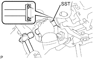
C097018E01
  1. Using SST and a hammer, install a new oil seal.

    SST
    09554-30011  

  1. Coat the oil seal lip with MP grease.


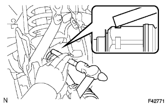
2. INSTALL FRONT DRIVE SHAFT ASSEMBLY LH


F042771
  1. Coat the spline of the inboard joint shaft with ATF.

  1. Align the shaft splines and install the drive shaft with a brass bar and hammer.

    NOTICE:
    1. Set the snap ring with the opening side facing downward.
    2. Be careful not to damage the oil seal.

    HINT:
    Whether the inboard joint shaft is in contact with the pinion shaft or not can be confirmed from the sound or feeling when driving it.


3. INSTALL FRONT DRIVE SHAFT ASSEMBLY RH

HINT:
Use the same procedure as for the LH side.


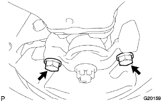
4. INSTALL FRONT SUSPENSION LOWER ARM LH


G020159
  1. Install the front lower ball joint attachment with the 2 bolts.

    Torque:
    160 N*m{ 1,631 kgf*cm , 118 ft.*lbf }


5. INSTALL FRONT SUSPENSION LOWER ARM RH

HINT:
Use the same procedure as for the LH side.


6. INSTALL TIE ROD END SUB-ASSEMBLY LH
  1. Install the tie rod end onto the steering knuckle arm.

  1. Install the nut.

    Torque:
    91 N*m{ 928 kgf*cm , 67 ft.*lbf }

  1. Install a new cotter pin.


7. INSTALL TIE ROD END SUB-ASSEMBLY RH

HINT:
The installation procedure for the RH side is the same as that for the LH side.


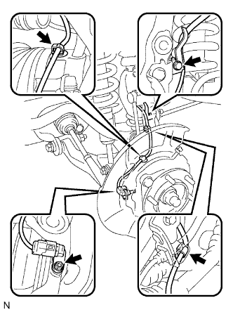
8. INSTALL FRONT SPEED SENSOR LH


F052163E03
  1. Install the speed sensor wire harness onto the steering knuckle with the bolt.

    Torque:
    13 N*m{ 133 kgf*cm , 10 ft.*lbf }

  1. Engage the 2 clamps.

  1. Install the speed sensor with the bolt.

    Torque:
    8.3 N*m{ 85 kgf*cm , 73 in.*lbf }


9. INSTALL FRONT SPEED SENSOR RH

HINT:
Use the same procedure as for the LH side.


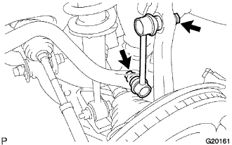
10. INSTALL FRONT STABILIZER LINK ASSEMBLY LH


G020161
  1. Install the front stabilizer link assembly LH with the 2 nuts.

    Torque:
    70 N*m{ 714 kgf*cm , 52 ft.*lbf }

    HINT:
    If the ball joint turns together with the nut, use a hexagon (6 mm) wrench to hold the stud.


11. INSTALL FRONT STABILIZER LINK ASSEMBLY RH

HINT:
The installation procedure for the RH side is the same as that for the LH side.


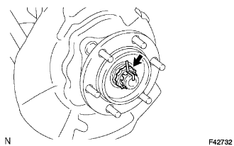
12. INSTALL FRONT AXLE HUB LH NUT


F042732
  1. Install the hub nut.

    Torque:
    235 N*m{ 2,396 kgf*cm , 173 ft.*lbf }

  1. Install the adjusting cap and cotter pin.


13. INSTALL FRONT AXLE HUB RH NUT

HINT:
Use the same procedure as for the LH side.


14. ADD DIFFERENTIAL OIL


D025304E03
  1. Stop the vehicle on a level place.

  1. Remove the differential filler plug and gasket.

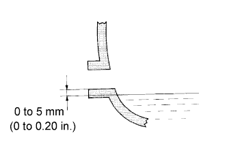
  1. Check that the oil level is within 5mm (0 to 0.20 in.) of the bottom of the filler plug opening.

    NOTICE:
    1. Excessively large or small quantities of oil may cause problems.
    2. After replacing the oil, drive the vehicle and check the oil level again.

    HINT:
    If necessary, fill the rear differential carrier assembly with hypoid gear oil.

    Oil grade:
    Hypoid gear oil API GL-5
    Recommended viscosity:
    Above -18°C (0°F) SAE 90
    Below -18°C (0°F) SAE 80W or 80W-90

    Capacity:
    Differential carrier assembly front:
    1.45 to 1.55 litters
    (1.54 to 1.64 US qts, 1.28 to 1.36 lmp. qts)

    Rear differential carrier assembly:
    2WD: 3.26 to 3.36 litters
    (3.45 to 3.55 US qts, 2.87 to 2.95 lmp. qts)
    Pre, 4WD: 2.75 to 2.85 litters
    (2.91 to 3.01 US qts, 2.42 to 2.50 lmp. qts)

  1. Check for oil leakage if the oil level is low.

  1. Install the differential filler plug and a new gasket.

    Torque:
    Front differential carrier assembly:
    39 N*m{ 398 kgf*cm , 29 ft.*lbf }
    Rear differential carrier assembly:
    49 N*m{ 500 kgf*cm , 36 ft.*lbf }


15. INSPECT DIFFERENTIAL OIL


D025304E03
  1. Stop the vehicle on a level place.

  1. Remove the differential filler plug and gasket.

  1. Check that the oil level is within 5mm (0 to 0.20 in.) of the bottom of the filler plug opening.

    NOTICE:
    1. Excessively large or small quantities of oil may cause problems.
    2. After replacing the oil, drive the vehicle and check the oil level again.

    HINT:
    If necessary, fill the rear differential carrier assembly with hypoid gear oil.

    Oil grade:
    Hypoid gear oil API GL-5
    Recommended viscosity:
    Above -18°C (0°F) SAE 90
    Below -18°C (0°F) SAE 80W or 80W-90

    Capacity:
    Differential carrier assembly front:
    1.45 to 1.55 litters
    (1.54 to 1.64 US qts, 1.28 to 1.36 lmp. qts)

    Rear differential carrier assembly:
    2WD: 3.26 to 3.36 litters
    (3.45 to 3.55 US qts, 2.87 to 2.95 lmp. qts)
    Pre, 4WD: 2.75 to 2.85 litters
    (2.91 to 3.01 US qts, 2.42 to 2.50 lmp. qts)

  1. Check for oil leakage if the oil level is low.

  1. Install the differential filler plug and a new gasket.

    Torque:
    Front differential carrier assembly:
    39 N*m{ 398 kgf*cm , 29 ft.*lbf }
    Rear differential carrier assembly:
    49 N*m{ 500 kgf*cm , 36 ft.*lbf }


16. INSTALL NO. 1 ENGINE UNDER COVER SUB-ASSEMBLY
  1. Install the No. 1 engine under cover sub-assembly with the 4 bolts.

    Torque:
    30 N*m{ 306 kgf*cm , 22 ft.*lbf }


17. INSTALL NO. 2 ENGINE UNDER COVER SUB-ASSEMBLY (w/ Engine Under Cover No, 2)
  1. Install the No. 2 engine under cover sub-assembly with the 4 bolts.

    Torque:
    30 N*m{ 306 kgf*cm , 22 ft.*lbf }


18. INSTALL FRONT WHEELS

Torque:
113 N*m{ 1,152 kgf*cm , 83 ft.*lbf }


19. INSPECT AND ADJUST FRONT WHEEL ALIGNMENT

HINT:
(Click here)


20. CONNECT CABLE TO NEGATIVE BATTERY TERMINAL

Torque:
3.9 N*m{ 40 kgf*cm , 35 in.*lbf }


21. CHECK VSC SENSOR SIGNAL (w/ VSC)

HINT:
(Click here)


22. CHECK ABS SENSOR SIGNAL (w/o VSC)

HINT:
(Click here)