VEHICLE STABILITY CONTROL SYSTEM > TEST MODE PROCEDURE |
| TEST MODE PROCEDURE (for Using a Intelligent Tester) |
Turn the ignition switch to OFF.
Check that the steering wheel is in the straight-ahead position.
A/T: Check that the shift lever is in the P position and apply the parking brake.
M/T: Check that the shift lever is in neutral and apply the parking brake.
![]() |
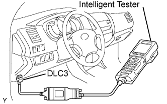
Connect the intelligent tester to the DLC3.
Turn the ignition switch to the ON position.
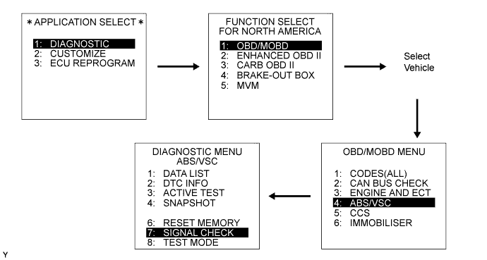
Switch the ECU to test mode using the intelligent tester. Select the following menu items: DIAGNOSIS / OBD/MOBD /select vehicle / ABS/VSC / SIGNAL CHECK.
![]() |
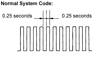
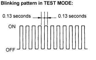
Check that the ABS and VSC TRAC warning lights blink as shown in the illustration.
| Trouble area | See page |
| ABS warning light circuit |
Click here
Click here |
| VSC TRAC warning light circuit |
Click here
Click here |
| TS and CG terminal circuit |
Click here
|
Start the engine.
Activate the ABS sensor (deceleration sensor, master cylinder pressure sensor, 4WD detection switch, L4 detection switch and speed sensor) and VSC sensor (yaw rate and deceleration sensor) in test mode (SIGNAL CHECK) using a intelligent tester.
| TEST MODE PROCEDURE (for Using a SST Check Wire) |
Turn the ignition switch to OFF.
Check that the steering wheel is in the straight-ahead position.
A/T: Check that the shift lever is in the P position and apply the parking brake.
M/T: Check that the shift lever is in neutral and apply the parking brake.
![]() |
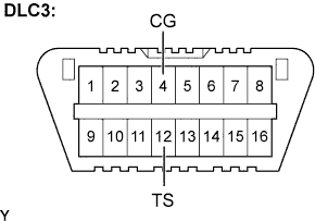
Using SST, connect terminals TS and CG of the DLC3.
Turn the ignition switch to the ON position.
![]() |
Check that the ABS and VSC TRAC warning lights blink as shown in the illustration.
| Trouble area | See page |
| ABS warning light circuit |
Click here
Click here |
| VSC TRAC warning light circuit |
Click here
Click here |
| TS and CG terminal circuit |
Click here
|
Start the engine.
Activate the ABS sensor (deceleration sensor, master cylinder pressure sensor, 4WD detection switch, L4 detection switch and speed sensor) and VSC sensor (yaw rate and deceleration sensor) in test mode (SIGNAL CHECK) using a check wire.
| DECELERATION SENSOR SIGNAL CHECK |
![]() |
Check that the ABS warning light is blinking as shown in the illustration.
Keep the vehicle stationary on a level surface for 1 second or more.
| MASTER CYLINDER PRESSURE SENSOR CHECK |
![]() |
Check that the ABS warning light is blinking as shown in the illustration.
Keep the vehicle stationary and release the brake pedal for 1 second or more, and quickly depress the brake pedal with a force of 98 N (10 kgf) or more for 1 second or more.
| 4WD DETECTION SWITCH SIGNAL CHECK (for 4WD) |
![]() |
Check that the ABS warning light is blinking as shown in the illustration.
Check the transfer indicator switch (4WD position).
Push the 4 wheel drive control switch on to put the vehicle in 4WD mode.
Push the 4 wheel drive control switch off to put the vehicle in 2WD mode.
| L4 DETECTION SWITCH SIGNAL CHECK (for 4WD) |
![]() |
Check that the ABS warning light is blinking as shown in the illustration.
Check the transfer indicator switch (L4 position).
Turn the 4 wheel drive control switch to the L position to put the vehicle in L4 mode.
Turn the 4 wheel drive control switch to the H position to put the vehicle in H4 mode.
| SPEED SENSOR CHECK |
![]() |
Check that the ABS warning light is blinking as shown in the illustration.
Check the speed sensor signal
Drive the vehicle straight forward at a speed of 56 mph (90 km/h) or more.
Drive the vehicle straight rearward at a speed of 1.9 mph (3 km/h) or more for 1 second or more.
Check that the ABS warning light goes off.
Stop the vehicle.
| READ DTC OF ABS SENSOR (for Using a Intelligent Tester) |
Read the DTC(s) by following the tester screen.
| READ DTC OF ABS SENSOR (for Using a SST Check Wire) |
Using SST, connect terminals TC and CG of the DLC3.
Turn the ignition switch to the ON position.
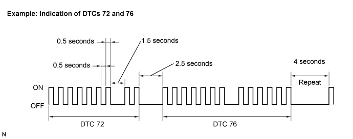
Read the number of blinks of the ABS warning light.
![]() |

After the check, disconnect the SST from terminals TC and CG of the DLC3.
Turn the ignition switch to OFF.
| YAW RATE SENSOR CHECK |
![]() |
Check that the VSC TRAC warning light is blinking as shown in the illustration.
Keep the vehicle stationary on a level surface for 1 second or more.
![]() |
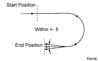
Shift the shift lever to the D position (A/T) and drive the vehicle at a speed of approximately 3 mph (5 km/h), turn the steering wheel either to the left or right 90°or more, and turn the vehicle through 180 degrees.
A/T: Stop the vehicle, check that the shift lever is in the P position, and then apply the parking brake.
M/T: Stop the vehicle, check that the shift lever is in neutral, and then apply the parking brake.
Check that the skid control (VSC warning) buzzer sounds for 3 seconds.
| DAC OPERATION SWITCH SIGNAL CHECK (for 4WD) |
![]() |
Check that the VSC TRAC warning light is blinking as shown in the illustration.
Check the DAC switch.
Push the DAC switch on.
Push the DAC switch off.
| READ DTC OF VSC SENSOR (for Using a Intelligent Tester) |
Read the DTC(s) by following the tester screen.
| READ DTC OF VSC SENSOR (for Using a SST Check Wire) |
Using SST, connect terminals TC and CG of the DLC3.
Turn the ignition switch to the ON position.
Read the number of blinks of the VSC TRAC warning light.
![]() |

After the check, disconnect the SST from terminals TC and CG of the DLC3.
Turn the ignition switch to OFF.
| DTC OF SIGNAL CHECK FUNCTION |
| DTC No. | Diagnosis | Trouble Areas |
| C1271/71 | Low output voltage of right front speed sensor |
|
| C1272/72 | Low output voltage of left front speed sensor |
|
| C1273/73 | Low output voltage of right rear speed sensor |
|
| C1274/74 | Low output voltage of left rear speed sensor |
|
| C1275/75 | Abnormal change in output voltage of right front speed sensor | Right front speed sensor rotor |
| C1276/76 | Abnormal change in output voltage of left front speed sensor | Left front speed sensor rotor |
| C1277/77 | Abnormal change in output voltage of right rear speed sensor | Right rear speed sensor rotor |
| C1278/78 | Abnormal change in output voltage of left rear speed sensor | Left rear speed sensor rotor |
| C1279/79 (*1), (*2) | Deceleration sensor faulty |
|
| C1282/82 (*2) | Center differential lock position switch malfunction | Transfer indicator switch (4WD position) |
| C1283/83 (*2) | L4 detection switch malfunction | Transfer indicator switch (L4 position) |
| DTC No. | Diagnosis | Trouble Areas |
| C0371/71 | Yaw rate sensor output signal malfunction | Yaw rate and deceleration sensor |
| C1379/74 | Malfunction in DAC operation switch | DAC switch |