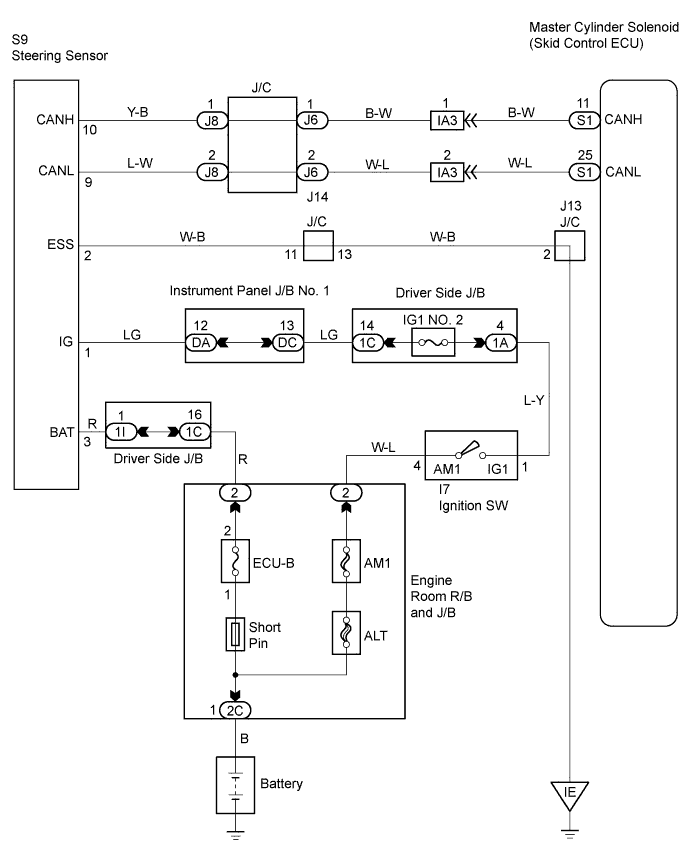
DTC C1231/31 Steering Angle Sensor Circuit Malfunction |
DTC C1290/66 Steering Angle Sensor Zero Point Malfunction |
| DTC No. | DTC Detecting Conditions | Trouble Areas |
| C1231/31 | When ECU IG1 terminal voltage 9.5 V or more, steering angle sensor malfunction signal received. |
|
| C1290/66 | Steering angle sensor zero point calibration position significantly differs from recorded value. | Steering angle sensor |
| 1.CHECK CAN COMMUNICATION SYSTEM |
Check CAN communication system DTC (Click here).
| Result | Proceed to |
| DTC not output | A |
| DTC output | B |
|
| ||||
| OK | |
 |
| 2.READ VALUE OF DATA LIST (STEERING ANGLE SENSOR) |
Connect the intelligent tester to the DLC3.
Turn the ignition switch to the ON position.
Turn the tester ON.
Select "DATA LIST" mode on the intelligent tester.
| Item | Measurement Item / Range (Display) | Normal Condition | Diagnostic Note |
| STEERING ANG | Steering sensor/ Min.: -1152 deg, Max.: 1150.875 deg | Left turn: Increase Right turn: Decrease | - |
Check that the steering angle sensor value displayed on the intelligent tester changes when turning the steering wheel.
| OK (When troubleshooting in accordance with DTC CHART) | A |
| OK (When troubleshooting in accordance with PROBLEM SYMPTOMS TABLE) | B |
| NG | C |
|
| ||||
|
| ||||
| A | |
|
| 3.RECONFIRM DTC |
Clear the DTCs (Click here).
Check if the same DTCs are recorded.
| Result | Proceed to |
| DTC output | A |
| DTC not output | B |
|
| ||||
| A | ||
 | ||
| ||
| 4.CHECK TERMINAL VOLTAGE (STEERING ANGLE SENSOR) |
Remove the steering wheel and the column lower cover.
Disconnect the steering angle sensor connector.
Turn the ignition switch to the ON position.
Measure the voltage.
| Tester Connection | Specified Condition |
| S9-1 (IG1) - S9-2 (ESS) | 10 to 14 V |
| S9-3 (BAT) - S9-2 (ESS) | 10 to 14 V |
Turn the ignition switch to OFF.
Reconnect the steering angle sensor connector.
Reinstall the steering wheel and the column lower cover.
|
| ||||
| OK | |
|
| 5.REPLACE STEERING ANGLE SENSOR |
Replace the steering angle sensor (Click here).
| NEXT | |
|
| 6.RECONFIRM DTC |
Clear the DTCs (Click here).
Check if the same DTCs are recorded.
| Result | Proceed to |
| DTC output | A |
| DTC not output | B |
|
| ||||
| A | ||
| ||
| ||

