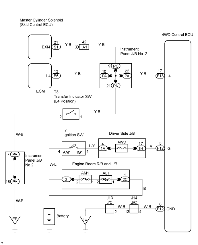
DTC C1268/68 Transfer "L4" Position Switch Circuit |
| DTC No. | DTC Detecting Condition | Trouble Areas |
| C1268/68 | L4 switch signal input to skid control ECU does not match L4 switch signal output from ECM. |
|
| 1.INSPECT SKID CONTROL ECU (EXI4 TERMINAL VOLTAGE) |
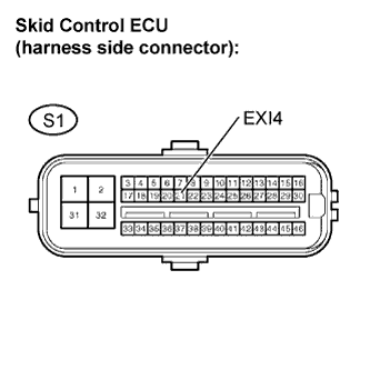 |
Disconnect the skid control ECU connector.
Turn the ignition switch to the ON position.
Measure the voltage.
| Tester Connection | Transfer Condition | Specified Condition |
| S1-21 (EXI4) - Body ground | L4 | Below 1.5 V |
| S1-21 (EXI4) - Body ground | Other than above | 8 to 14 V |
Turn the ignition switch to OFF.
Reconnect the skid control ECU connector.
|
| ||||
| OK | |
 |
| 2.PERFORM TEST MODE INSPECTION (SIGNAL CHECK) |
Check if the test mode DTC (C1283/83) is detected.
| Result | Proceed to |
| Test mode DTC (C1283/83) not output | A |
| Test mode DTC (C1283/83) output | B |
|
| ||||
| A | |
|
| 3.RECONFIRM DTC |
Clear the DTCs (Click here).
Check if the same DTCs are recorded.
| Result | Proceed to |
| DTC output | A |
| DTC not output | B |
|
| ||||
| A | ||
 | ||
| ||
| 4.INSPECT TRANSFER INDICATOR SWITCH (L4 POSITION) |
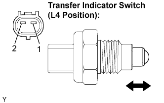 |
Disconnect the transfer indicator switch (L4 position) connector.
Remove the transfer indicator switch (L4 position).
Measure the voltage.
| Tester Connection | Switch Position | Specified Condition |
| 1 - 2 | Pushed | Below 1 Ω |
| 1 - 2 | Free | 10 kΩ or higher |
Reinstall the transfer indicator switch (L4 position).
Reconnect the transfer indicator switch (L4 position) connector.
|
| ||||
| OK | |
|
| 5.CHECK HARNESS AND CONNECTOR (SKID CONTROL ECU - TRANSFER INDICATOR SWITCH (L4 POSITION)) |
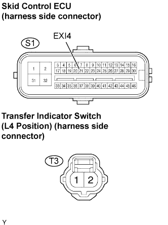 |
Disconnect the skid control ECU connector.
Disconnect the transfer indicator switch (L4 position) connector.
Measure the resistance.
| Tester Connection | Specified Condition |
| S1-21 (EXI4) - T3-1 | Below 1 Ω |
| S1-21 (EXI4) - Body ground | 10 kΩ or higher |
Reconnect the transfer indicator switch (L4 position) connector.
Reconnect the skid control ECU connector.
|
| ||||
| OK | |
|
| 6.CHECK HARNESS AND CONNECTOR (SKID CONTROL ECU - ECM) |
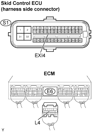 |
Disconnect the skid control ECU connector.
Disconnect the ECM connector.
Measure the resistance.
| Tester Connection | Specified Condition |
| S1-21 (EXI4) - E6-13 (L4) | Below 1 Ω |
Measure the resistance.
| Tester Connection | Specified Condition |
| S1-21 (EXI4) - Body ground | 10 kΩ or higher |
| E6-13 (L4) - Body ground | 10 kΩ or higher |
Reconnect the ECM connector.
Reconnect the skid control ECU connector.
|
| ||||
| OK | ||
| ||
| ||

