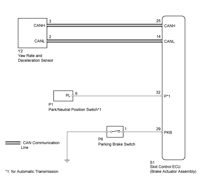
DTC C1210 Zero Point Calibration of Yaw Rate Sensor Undone |
DTC C1336 Zero Point Calibration of Acceleration Sensor Undone |
| DTC Code | DTC Detection Condition | Trouble Area |
| C1210 | When either of following 1 or 2 detected:
|
|
| C1336 | When either of following 1 or 2 detected:
|
|
| 1.PERFORM ZERO POINT CALIBRATION OF YAW RATE AND DECELERATION SENSOR |
Perform zero point calibration of the yaw rate and deceleration sensor (Click here).
| NEXT | |
 |
| 2.RECONFIRM DTC |
Turn the ignition switch off.
Clear the DTC (Click here).
At a speed of 30 km/h (19 mph) or more, drive the vehicle, turn the steering wheel, and decelerate (depress the brake pedal) the vehicle.
Check if the same DTC is recorded (Click here).
| Result | Proceed to |
| DTC is output | A |
| DTC is not output | B |
|
| ||||
| A | |
|
| 3.CHECK YAW RATE AND DECELERATION SENSOR INSTALLATION |
Turn the ignition switch off.
Check that the yaw rate and deceleration sensor has been installed properly (Click here).
|
| ||||
| OK | |
|
| 4.CHECK HARNESS AND CONNECTOR (ECU - PARK/NEUTRAL POSITION SWITCH OR PARKING BRAKE SWITCH) |
for Automatic transmission
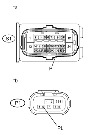 |
Disconnect the Park/Neutral position switch connector. switch connector.
Disconnect the skid control ECU (brake actuator assembly) connector.
Measure the resistance according to the value(s) in the table below.
| Tester Connection | Condition | Specified Condition |
| S1-32 (P) - P1-6 (PL) | Always | Below 1 Ω |
| *a | Front view of wire harness connector (to Skid Control ECU (Brake Actuator Assembly)) |
| *b | Front view of wire harness connector (to Park/Neutral Position Switch) |
for Manual transmission
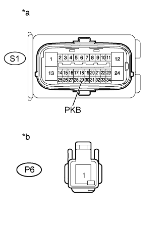 |
Disconnect the skid control ECU (brake actuator assembly) connector.
Disconnect the parking brake switch connector.
Measure the resistance according to the value(s) in the table below.
| Tester Connection | Condition | Specified Condition |
| S1-29 (PKB) - P6-1 | Always | Below 1 Ω |
| *a | Front view of wire harness connector (to Skid Control ECU (Brake Actuator Assembly)) |
| *b | Front view of wire harness connector (to Parking Brake Switch) |
|
| ||||
| OK | |
|
| 5.INSPECT PARK/NEUTRAL POSITION SWITCH OR PARKING BRAKE SWITCH |
Inspect the Park/Neutral Position (PNP) switch (for Automatic transmission).
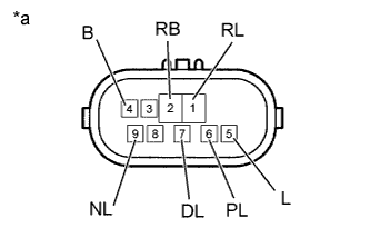 |
Disconnect the PNP switch connector.
Check the resistance when the transmission gear selector lever is moved to each position.
| Tester Connection | Switch Condition | Specified Condition |
| 4 (B) - 5 (L) | Shift lever position P and N | Below 1 Ω |
| Shift lever position not P and N | 10 kΩ or higher | |
| 2 (RB) - 6 (PL) | Shift lever position P | Below 1 Ω |
| Shift lever position not P | 10 kΩ or higher | |
| 2 (RB) - 1 (RL) | Shift lever position R | Below 1 Ω |
| Shift lever position not R | 10 kΩ or higher | |
| 2 (RB) - 9 (NL) | Shift lever position N | Below 1 Ω |
| Shift lever position not N | 10 kΩ or higher | |
| 2 (RB) - 7 (DL) | Shift lever position D and 4 | Below 1 Ω |
| Shift lever position not D and 4 | 10 kΩ or higher | |
| 2 (RB) - 3 (2L) | Shift lever position 3 | Below 1 Ω |
| Shift lever position not 3 | 10 kΩ or higher | |
| 2 (RB) - 8 (LL) | Shift lever position 2 and L | Below 1 Ω |
| Shift lever position not 2 and L | 10 kΩ or higher |
| *a | Component without harness connected (Park/Neutral Position Switch) |
Inspect the parking brake switch (for Manual transmission).
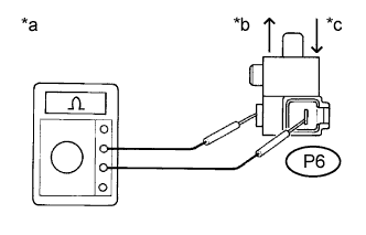 |
Disconnect the parking brake switch connector.
Measure the resistance according to the value(s) in the table below.
| Tester Connection | Switch Condition | Specified Condition |
| P6-1 Ground part | Released | Below 1 Ω |
| P6-1 Ground part | Pushed in | 10 kΩ or higher |
| *a | Component without harness connected (Parking Brake Switch) |
| *b | Release |
| *c | Push |
|
| ||||
| OK | |
|
| 6.REPLACE YAW RATE AND DECELERATION SENSOR |
Replace the yaw rate and deceleration sensor (Click here).
| NEXT | |
|
| 7.PERFORM YAW RATE AND DECELERATION SENSOR ZERO POINT CALIBRATION |
Perform the zero point calibration of the yaw rate and deceleration sensor (Click here).
| NEXT | |
|
| 8.RECONFIRM DTC |
Clear the DTCs (Click here).
Check if the same DTCs are recorded (Click here).
| Result | Proceed to |
| DTC is output | A |
| DTC is not output | B |
|
| ||||
| A | ||
 | ||
| ||
