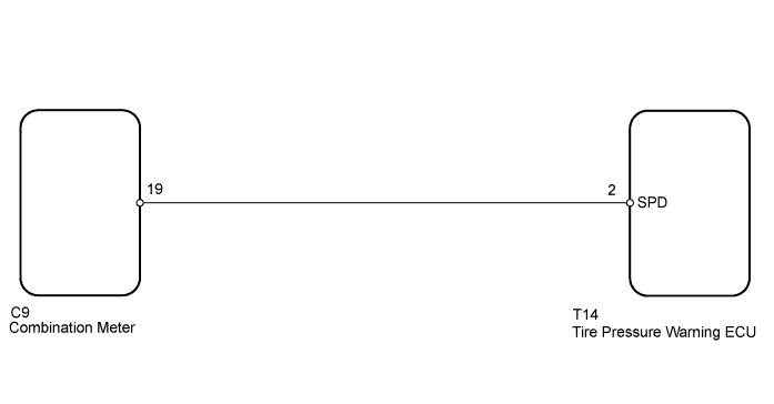
DTC C2191/91 Vehicle Speed Signal Error (Test Mode DTC) |
| DTC Code | DTC Detection Condition | Trouble Area |
| C2191/91 | Test mode procedure is performed |
|
| 1.READ VALUE USING TECHSTREAM (VEHICLE SPEED) |
Turn the ignition switch OFF.
Connect the Techstream to the DLC3.
Turn the ignition switch ON and the Techstream on.
Enter the following menus: Chassis / Tire Pressure Monitor / Data List /
Check that the values indicated on the Techstream and on the combination meter are the same.
| Tester Display | Measurement Item/Range | Normal Condition | Diagnostic Note |
| Vehicle Speed | Vehicle speed/ min.: 0 km/h (0 mph) max.: 255 km/h (158 mph) | Almost same as actual vehicle speed | Speed indicated on combination meter |
|
| ||||
| OK | ||
 | ||
| ||
| 2.INSPECT TIRE PRESSURE WARNING ECU (SPD SIGNAL) |
 |
Disconnect the T14 ECU connector.
Jack up the vehicle.
Shift the lever to the neutral position.
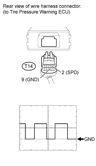
Check the waveform of the ECU connector using an oscilloscope, while turning any of the wheels slowly.
| Item | Contents |
| Tool Setting | 5 V/DIV., 20 ms/DIV. |
| Vehicle Condition | Any wheel is rotated slowly |
| Tester Connection | Switch Condition | Specified Condition |
| T14-2 (SPD) - T14-9 (GND) | Ignition switch ON | Correct waveform is as shown |
|
| ||||
| OK | ||
| ||
| ||
| 3.CHECK HARNESS AND CONNECTOR (ECU - COMBINATION METER) |
 |
Disconnect the T14 ECU connector.
Disconnect the C9 meter connector.
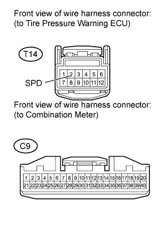
Measure the resistance according to the value(s) in the table below.
| Tester Connection | Condition | Specified Condition |
| T14-2 (SPD) - C9-19 | Always | Below 1 Ω |
| T14-2 (SPD) - Body ground | Always | 10 kΩ or higher |
|
| ||||
| OK | ||
| ||
| ||

