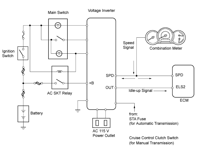
DTC P1500 AC Inverter Malfunction |
| DTC No. | DTC Detection Condition | Trouble Area |
| P1500 | While vehicle running, idle-up signal input to ECM for 10 seconds (2 trip detection logic) |
|
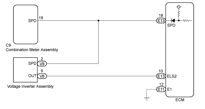
| 1.CHECK ANY OTHER DTCS OUTPUT (IN ADDITION TO DTC P1500) |
Connect the Techstream to the DLC3.
Turn the ignition switch to ON.
Turn the Techstream on.
Enter the following menus: Powertrain / Engine and ECT / Trouble Codes.
Read DTCs.
| Result | Proceed to |
| P1500 | A |
| P1500 and other DTCs | B |
|
| ||||
| A | |
 |
| 2.INSPECT VOLTAGE INVERTER ASSEMBLY (SPD SIGNAL) |
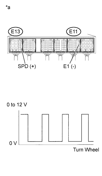 |
Move the shift lever to N (Neutral) position.
Jack up the vehicle.
Turn the ignition switch to ON.
Measure the voltage according to the value(s) in the table below.
| Tester Connection | Switch Condition | Specified Condition |
| E13-18 (SPD) - E11-12 (E1) | Ignition switch ON Wheel turned slowly | Voltage generated intermittently |
| *a | Component with harness connected (ECM) |
|
| ||||
| OK | |
|
| 3.INSPECT ECM |
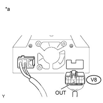 |
Disconnect the voltage inverter assembly connector.
Start the engine.
Measure the voltage according to the value(s) in the table below.
| Tester Connection | Condition | Specified Condition |
| V8-9 (OUT) - Body ground | Idling | 1 V or less |
| *a | Rear view of wire harness connector (to Voltage Inverter Assembly) |
|
| ||||
| OK | ||
 | ||
| ||
| 4.CHECK HARNESS AND CONNECTOR (ECM - INVERTER, INVERTER - POWER SOURCE) |
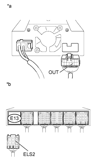 |
Disconnect the voltage inverter connector.
Disconnect the ECM connector.
Turn the ignition switch to ON.
Measure the voltage according to the value(s) in the table below.
| Tester Connection | Switch Condition | Specified Condition |
| V8-9 (OUT) - Body ground | Ignition switch ON | 1 V or less |
| E13-10 (ELS2) - Body ground | Ignition switch ON | 1 V or less |
| *a | Rear view of wire harness connector (to Voltage Inverter Assembly) |
| *b | Rear view of wire harness connector (to ECM) |
|
| ||||
| OK | ||
| ||
| ||

