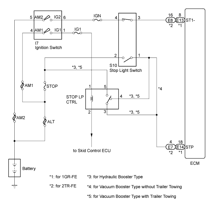
DTC P0571 Stop Light Switch Circuit Malfunction |
| DTC No. | DTC Detected Conditions | Trouble Areas |
| P0571 | ECM detects a malfunction of the stop light switch circuit under both of the following conditions.
|
|
| 1.CHECK FOR DTC (VEHICLE STABILITY CONTROL SYSTEM) |
Check for DTCs in Vehicle Stability Control System.
| Result | Proceed to |
| OK | A |
| NG (for Hydraulic Booster Type) | B |
| NG (for Vacuum Booster Type) | C |
|
| ||||
|
| ||||
| A | |
 |
| 2.CHECK HARNESS AND CONNECTOR (STOP LIGHT SWITCH - BATTERY) |
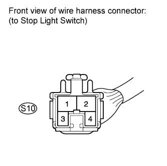 |
Disconnect the S10 connector from the stop light switch.
Measure the voltage according to the value(s) in the table below.
| Tester Connection | Switch Condition | Specified Condition |
| S10-2 - Body ground | Always | 11 to 14 V |
| S10-4 - Body ground | Ignition switch ON | 11 to 14 V |
Reconnect the stop light switch connector.
|
| ||||
| OK | |
|
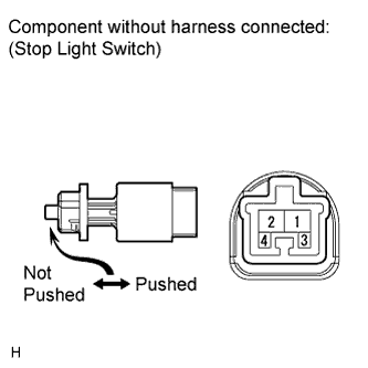
| 3.INSPECT STOP LIGHT SWITCH |
 |
Turn the ignition switch off.
Remove the stop light switch.
Measure the resistance according to the value(s) in the table below.
| Tester Connection | Switch Condition | Specified Condition |
| S10-1 - S10-2 | Switch pin not pushed | Below 1Ω |
| S10-3 - S10-4 | Switch pin not pushed | 10 kΩ or higher |
| S10-1 - S10-2 | Switch pin pushed | 10 kΩ or higher |
| S10-3 - S10-4 | Switch pin pushed | Below 1Ω |
Reinstall the stop light switch.
| Result | Proceed to |
| OK (for 1GR-FE) | A |
| OK (for 2TR-FE) | B |
| NG | C |
|
| ||||
|
| ||||
| A | |
|
| 4.INSPECT ECM |
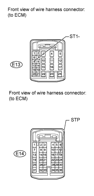 |
Disconnect the E13 and E14 ECM connector.
Measure the voltage according to the value(s) in the table below.
| Tester Connection | Condition | Specified Condition |
| E14-18 (STP) - Body ground | Brake pedal depressed | 11 to 14 V |
| E14-18 (STP) - Body ground | Brake pedal released | Below 1V |
| E13-8 (ST1-) - Body ground | Brake pedal depressed | Below 1V |
| E13-8 (ST1-) - Body ground | Brake pedal released | 11 to 14 V |
Reconnect the ECM connector.
|
| ||||
| OK | ||
 | ||
| ||
| 5.INSPECT ECM |
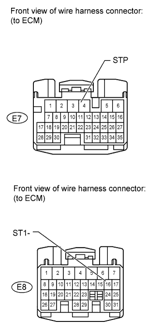 |
Disconnect the E7 and E8 ECM connector.
Measure the voltage according to the value(s) in the table below.
| Tester Connection | Condition | Specified Condition |
| E7-4 (STP) - Body ground | Brake pedal depressed | 11 to 14 V |
| E7-4 (STP) - Body ground | Brake pedal released | Below 1V |
| E8-16 (ST1-) - Body ground | Brake pedal depressed | Below 1V |
| E8-16 (ST1-) - Body ground | Brake pedal released | 11 to 14 V |
Reconnect the ECM connector.
|
| ||||
| OK | ||
| ||
| ||

