
DTC 01-DD Master Reset |
DTC 01-E1 Voice Processing Device ON Error |
| DTC No. | DTC Detection Condition | Trouble Area |
| 01-DD*1 | The device that should be the master has been disconnected after the engine starts. |
|
| 01-E1*2 | The AMP device stores that the AMP output does not function even while the source device operates. |
| 1.CHECK RADIO RECEIVER ASSEMBLY POWER SOURCE CIRCUIT |
| NEXT | |
|
| 2.INSPECT RADIO RECEIVER ASSEMBLY |
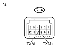 |
Disconnect the R14 radio receiver assembly connector.
Measure the resistance according to the value(s) in the table below.
| Tester Connection | Condition | Specified Condition |
| R14-9 (TXM+) - R14-10 (TXM-) | Always | 60 to 80 Ω |
| *a | Component without harness connected (Radio Receiver Assembly) |
|
| ||||
| OK | |
|
| 3.IDENTIFY COMPONENT WHICH HAS STORED THIS CODE |
Enter diagnostic mode.
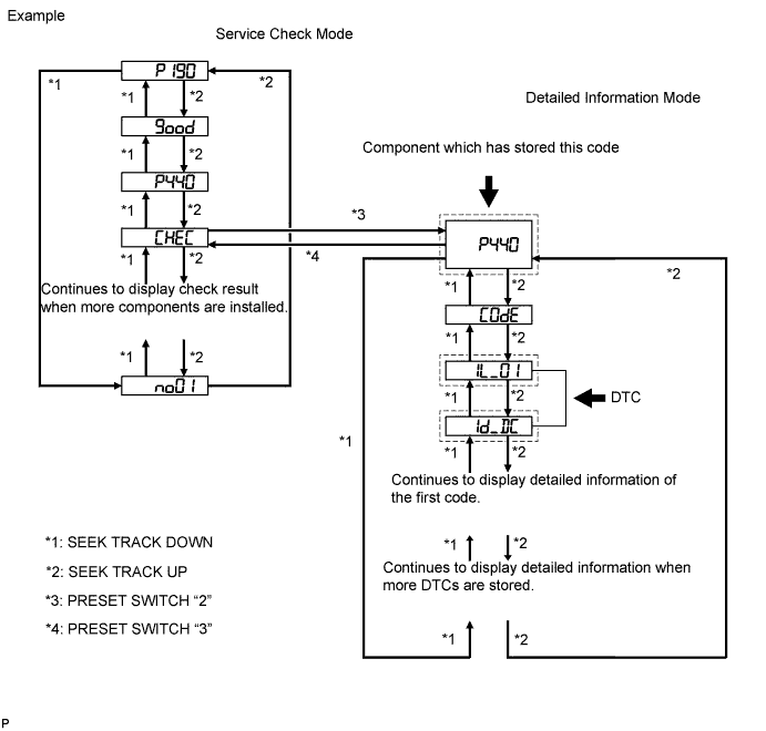
Press preset switch "2" to change the mode to "Detailed Information Mode".
Identify the component which has stored this code.
| Component | Physical Address |
| Radio receiver assembly | 190 |
| Multi-media interface ECU | 388 |
| Satellite radio tuner | 1F1 |
| NEXT | |
|
| 4.CHECK COMPONENT SHOWN BY SUB-CODE |
Select the component shown by the sub-code.
| Component | Proceed to |
| Except satellite radio tuner | A |
| Satellite radio tuner (1F1) | B |
|
| ||||
| A | |
|
| 5.CHECK HARNESS AND CONNECTOR |
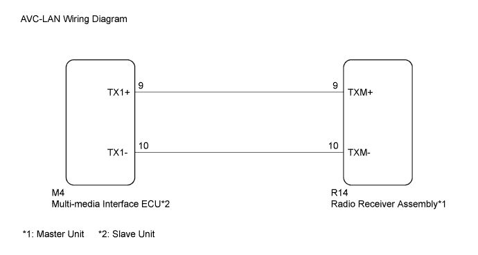
Referring to the following AVC-LAN wiring diagram, check the AVC-LAN circuit between the radio receiver assembly and component which has stored this code.
Disconnect all connectors between the radio receiver assembly and component which has stored this code.
Check for an open or short in the AVC-LAN circuit between the radio receiver assembly and component which has stored this code.
|
| ||||
| OK | |
|
| 6.REPLACE RADIO RECEIVER ASSEMBLY |
Replace the radio receiver assembly with a known good one (Click here).
| NEXT | |
|
| 7.CLEAR DTC |
Clear the DTCs (Click here).
| NEXT | |
|
| 8.RECHECK FOR DTC |
Recheck for DTCs and check if the same DTC is output again.
|
| ||||
| OK | ||
 | ||
| ||
