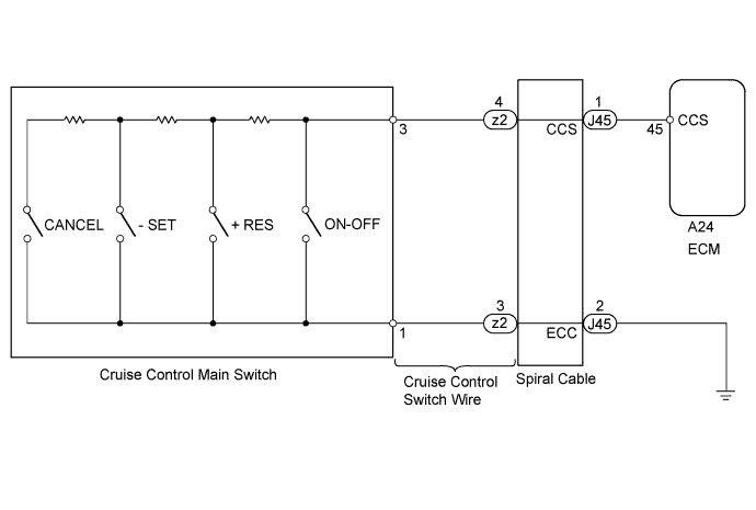
CRUISE CONTROL SYSTEM > Cruise Control Switch Circuit |
| 1.READ VALUE USING TECHSTREAM (CRUISE CONTROL MAIN SWITCH) |
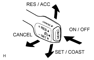 |
Using the Techstream, read the Data List.
| Tester Display | Measurement Item/Range | Normal Condition | Diagnostic Note |
| CCS Main SW M-CPU | Main switch signal (Main CPU) / ON or OFF | ON: Main switch ON (Pushed on) OFF: Main switch OFF (Pushed off) | - |
| Cancel Switch | CANCEL switch signal / ON or OFF | ON: CANCEL switch ON OFF: CANCEL switch OFF | - |
| SET/COAST Switch | SET / COAST switch signal / ON or OFF | ON: SET / COAST switch ON OFF: SET / COAST switch OFF | - |
| RES/ACC Switch | RES / ACC switch signal / ON or OFF | ON: RES / ACC switch ON OFF: RES / ACC switch OFF | - |
|
| ||||
| OK | ||
 | ||
| ||
| 2.INSPECT CRUISE CONTROL MAIN SWITCH |
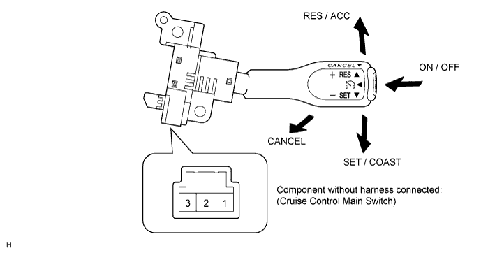
Remove the cruise control main switch (Click here).
Measure the resistance according to the value(s) in the table below.
| Tester Connection | Switch Condition | Specified Condition |
| 1 - 3 | Neutral | 10 kΩ or higher |
| RES / ACC | 235 to 245 Ω | |
| SET / COAST | 620 to 640 Ω | |
| CANCEL | 1510 to 1570 Ω | |
| Main Switch OFF | 10 kΩ or higher | |
| Main Switch ON | Below 1 Ω |
|
| ||||
| OK | |
 |
| 3.INSPECT SPIRAL CABLE |
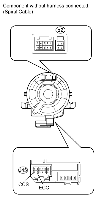 |
If there are any defects as follows, replace the spiral cable with a new one: Scratches, cracks, dents or chips on the connector or the spiral cable.
Check spiral cable.
Set the spiral cable to the center position .
After setting the spiral cable to the center position, rotate the spiral cable 2.5 times clockwise, and measure the resistance according to the value(s) in the table below. Then rotate the spiral cable 5 times counterclockwise, and measure the resistance according to the value(s) in the table below.
| Tester Connection | Condition | Specified Condition |
| z2-4 - J45-1 (CCS) | Always | Below 1 Ω |
| z2-3 - J45-2 (ECC) |
After setting the spiral cable to the center position, rotate the spiral cable 2.5 times clockwise. Then while rotating the spiral cable 5 times counterclockwise, measure the resistance according to the value(s) in the table below.
| Tester Connection | Condition | Specified Condition |
| z2-4 - J45-1 (CCS) | Always | Below 1 Ω |
| z2-3 - J45-2 (ECC) |
|
| ||||
| OK | |
|
| 4.INSPECT CRUISE CONTROL SWITCH WIRE |
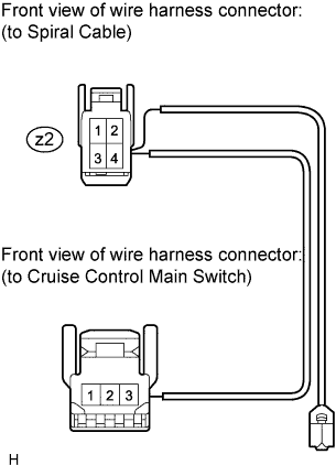 |
Remove the cruise control switch wire.
Measure the resistance according to the value(s) in the table below.
| Tester Connection | Condition | Specified Condition |
| z2-4 - 3 | Always | Below 1 Ω |
| z2-3 - 1 |
|
| ||||
| OK | |
|
| 5.CHECK HARNESS AND CONNECTOR (SPIRAL CABLE - ECM AND BODY GROUND) |
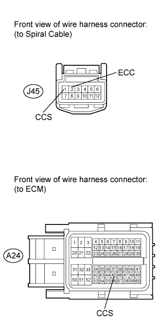 |
Disconnect the J45 spiral cable connector.
Disconnect the A24 ECM connector.
Measure the resistance according to the value(s) in the table below.
| Tester Connection | Condition | Specified Condition |
| J45-1 (CCS) - A24-45 (CCS) | Always | Below 1 Ω |
| J45-1 (CCS) - Body ground | Always | 10 kΩ or higher |
| J45-2 (ECC) - Body ground | Always | Below 1 Ω |
| Result | Proceed to |
| NG | A |
| OK (for 1GR-FE) | B |
| OK (for 2UZ-FE) | C |
| OK (for 3UR-FE) | D |
| OK (for 3UR-FBE) | E |
|
| ||||
|
| ||||
|
| ||||
|
| ||||
| A | ||
| ||
| ||

