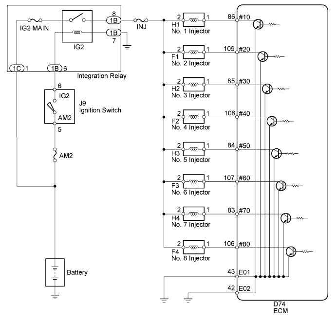
DTC P0300 Random / Multiple Cylinder Misfire Detected |
DTC P0301 Cylinder 1 Misfire Detected |
DTC P0302 Cylinder 2 Misfire Detected |
DTC P0303 Cylinder 3 Misfire Detected |
DTC P0304 Cylinder 4 Misfire Detected |
DTC P0305 Cylinder 5 Misfire Detected |
DTC P0306 Cylinder 6 Misfire Detected |
DTC P0307 Cylinder 7 Misfire Detected |
DTC P0308 Cylinder 8 Misfire Detected |
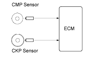
| DTC No. | DTC Detection Condition | Trouble Area |
| P0300 | Simultaneous misfiring of several cylinders occurs and one of following conditions below is detected (2 trip detection logic):
|
|
| P0301 P0302 P0303 P0304 P0305 P0306 P0307 P0308 | Misfiring of specific cylinder occurs and one of following conditions below is detected (2 trip detection logic):
|
| Related DTCs | P0300: Multiple cylinder misfire P0301: Cylinder 1 misfire P0302: Cylinder 2 misfire P0303: Cylinder 3 misfire P0304: Cylinder 4 misfire P0305: Cylinder 5 misfire P0306: Cylinder 6 misfire P0307: Cylinder 7 misfire P0308: Cylinder 8 misfire |
| Required Sensors/Components (Main) | Crankshaft position sensor and Camshaft position sensor |
| Required Sensors/Components (Related) | Engine coolant temperature and intake air temperature sensors and Mass air flow meter |
| Frequency of Operation | Continuous |
| Duration | 1000 to 4000 crankshaft revolutions: Emission related misfire 200 to 600 crankshaft revolutions: Catalyst damaged misfire |
| MIL Operation | 2 driving cycles: MIL illuminates when misfire detect MIL flashes immediately: When catalyst damaged misfire occur |
| Sequence of Operation | None |
| Monitor runs whenever following DTCs not present | P0016, P0018 (VVT System - Misalignment) P0017, P0019 (Exhaust VVT System - Misalignment) P0102, P0103 (Mass Air Flow Sensor) P0112, P0113 (Intake Air Temperature Sensor) P0115, P0117, P0118 (Engine Coolant Temperature Sensor) P0125 (Insufficient Coolant Temperature for Closed Loop Fuel Control) P0120, P0121, P0122, P0123, P0220, P0222, P0223, P2135 (Throttle Position Sensor) P0327, P0328, P0332, P0333, P032C, P032D, P033C, P033D (Knock Sensor) P0335 (Crankshaft Position Sensor) P1340 (Camshaft Position Sensor) P0351 - P0358 (Igniter) P0500 (Vehicle Speed Sensor) P0705 (Shift Lever Position Switch) |
| Battery voltage | 8 V or more |
| VVT system | Not operated by scan tool |
| Engine speed | 400 to 5900 rpm |
| Either of following conditions (a) or (b) met | - |
| (a) ECT at engine start | More than -7°C (19°F) |
| (b) ECT | More than 20°C (68°F) |
| Fuel cut | OFF |
| First 1000 revolutions after engine start, or Check Mode | Crankshaft 1000 revolutions |
| Except above | Crankshaft 1000 revolutions x 4 |
| All of following conditions 1, 2 and 3 met | Crankshaft 200 revolutions x 3 |
| 1. Driving cycles | 1st |
| 2. Check mode | OFF |
| 3. Engine speed | Less than 2800 rpm |
| Except above | Crankshaft 200 revolutions |
| Misfire rate | 2.5% or more |
| Number of misfire per 200 revolutions | 103 or more (varies with intake air amount and RPM) |
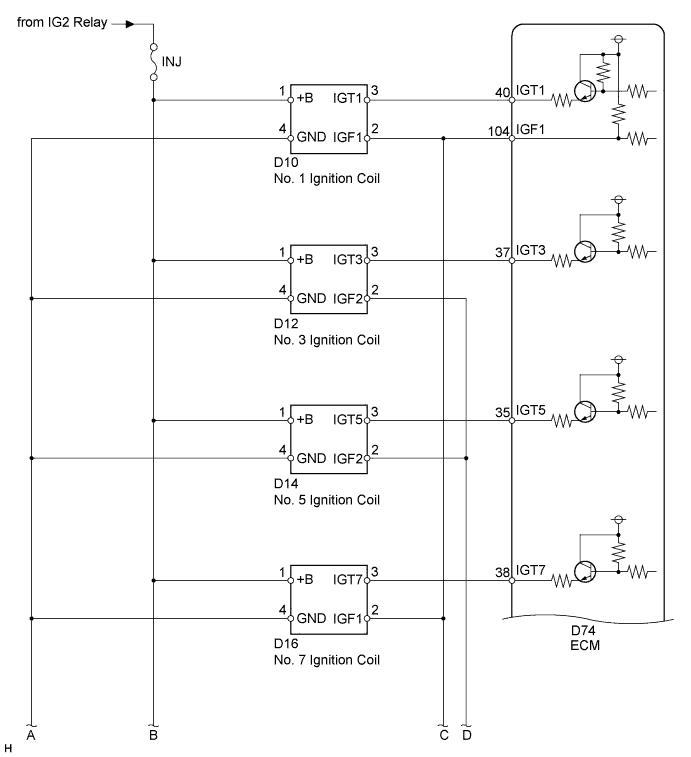
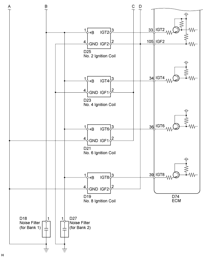
| Engine Speed | Duration |
| Idling | 3.5 minutes or more |
| 1000 | 3 minutes or more |
| 2000 | 1.5 minutes or more |
| 3000 | 1 minute or more |
| 1.CHECK ANY OTHER DTCS OUTPUT (IN ADDITION TO MISFIRE CODES) |
Connect the Techstream to the DLC3.
Turn the ignition switch to ON.
Turn the Techstream ON.
Enter the following menus: Powertrain / Engine and ECT / Trouble Codes.
Read DTCs.
| Result | Proceed to |
| P0300, P0301, P0302, P0303, P0304, P0305, P0306, P0307 and/or P0308 are output | A |
| P0300, P0301, P0302, P0303, P0304, P0305, P0306, P0307 and/or P0308 and other DTCs are output | B |
|
| ||||
| A | |
 |
| 2.READ VALUE USING TECHSTREAM (MISFIRE RPM AND MISFIRE LOAD) |
Connect the Techstream the DLC3.
Turn the ignition switch to ON and turn the Techstream ON.
Enter the following menus: Powertrain / Engine and ECT / Data List / Misfire / Misfire RPM and Misfire Load.
Read and note the Misfire RPM and Misfire Load values.
| NEXT | |
|
| 3.CHECK PCV HOSE CONNECTIONS |
Check the PCV hose connections.
|
| ||||
| OK | |
|
| 4.READ VALUE USING TECHSTREAM |
Connect the Techstream to the DLC3.
Turn the ignition switch to ON and turn the Techstream ON.
Enter the following menus: Powertrain / Engine and ECT / Data List / Catalyst OT MF F/C.
Read the value displayed on the Techstream.
| Data List | Display Item | Proceed to |
| Catalyst OT MF F/C | Avail | A |
| Not Avl | B |
|
| ||||
| A | |
|
| 5.PERFORM ACTIVE TEST USING TECHSTREAM |
Connect the Techstream to the DLC3.
Turn the ignition switch to ON and turn the Techstream ON.
Enter the following menus: Powertrain / Engine and ECT / Active Test / Prohibit the Catalyst OT Misfire prevent F/C.
Perform the Active Test.
| NEXT | |
|
| 6.READ VALUE USING TECHSTREAM (MISFIRE COUNT) |
Connect the Techstream to the DLC3.
Turn the ignition switch to ON.
Turn the Techstream on.
Clear the DTCs (Click here).
Start the engine.
Warm up the engine until the engine coolant temperature is 75°C (167°F) or more.
Drive the vehicle at 32 km/h (20 mph) or more and maintain a constant speed for 2 minutes or more.
After this driving make sure that the Data List "Alcohol Density Learning" is "Compl".
Enter the following menus: Powertrain / Engine and ECT / Data List / Misfire / Cylinder #1 Misfire Count, #2, #3, #4, #5, #6, #7 and #8.
Allow the engine to idle.
Read each value for Cylinder #1 Misfire Count to #8 displayed on the Techstream. If no misfire counts occur in any cylinders, perform the following procedures:
Move the shift lever to D.
Check the Cylinder #1 Misfire Count to #8.
If misfire counts are still not displayed, perform following procedure "1" and "2" and then check the misfire counts again.
Drive the vehicle with the Misfire RPM and Misfire Load noted in the "Read value using Techstream (Misfire RPM and Misfire Load)" procedures above (Procedure "1").
Read the Cylinder #1 Misfire Count to #8 or DTCs displayed on the Techstream (Procedure "2").
| Result | Proceed to |
| Most misfires occur in only 1 or 2 cylinders* | A |
| Except above | Proceed to following* |
| Result | Proceed to |
| A/F sensor and O2 sensor output both consistently indicate rich or lean or Aggregate fuel trim*1 less than -20% or Aggregate fuel trim*1 more than 65% | C |
| Except above | B |
| Air-fuel Ratio | A/F Sensor | HO2 Sensor |
| Lean | Higher than 3.25 V | Below 0.4 V |
| Rich | Below 3.25 V | Higher than 0.55 V |
| AFS Voltage B1 S1 | 3.28 V |
| AFS Voltage B2 S1 | 3.28 V |
| O2S B1 S2 | 0.76 V |
| O2S B2 S2 | 0.70 V |
| Short FT #1 | 1% |
| Long FT #1 | -6% |
| Short FT #2 | 2% |
| Long FT #2 | -6% |
| AF Lambda B1 S1 | 0.99 |
| AF Lambda B2 S1 | 0.99 |
| Alcohol Density Estimate | 0% |
| Alcohol Density Learning | Compl |
| AFS Voltage B1 S1 | 3.45 V |
| AFS Voltage B2 S1 | 3.56 V |
| O2S B1 S2 | 0.03 V |
| O2S B2 S2 | 0.03 V |
| Short FT #1 | 20.3% |
| Long FT #1 | -1.6% |
| Short FT #2 | 19.5% |
| Long FT #2 | -6.3% |
| AF Lambda B1 S1 | 1.04 |
| AF Lambda B2 S1 | 1.08 |
| Alcohol Density Estimate | 85% |
| Alcohol Density Learning | Compl |
|
| ||||
|
| ||||
| A | |
|
| 7.INSPECT SPARK PLUG |
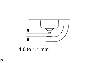 |
Remove the ignition coil and the spark plug of the misfiring cylinder (Click here).
Measure the spark plug electrode gap.
Check the electrode for carbon deposits.
| Manufacturer | Product |
| DENSO | SK20HR11 |
|
| ||||
| OK | |
|
| 8.CHECK FOR SPARKS AND IGNITION |
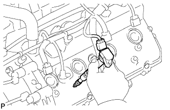 |
Disconnect the injector connectors to prevent the engine from starting.
Remove the ignition coil from the cylinder head (Click here).
Install the spark plug onto the ignition coil.
Attach the spark plug assembly to the cylinder head.
Crank the engine for less than 2 seconds and check the spark.
Install the ignition coil.
Reconnect the injector connectors.
|
| ||||
| OK | |
|
| 9.CHECK CYLINDER COMPRESSION PRESSURE |
Measure the cylinder compression pressure of the misfiring cylinder .
|
| ||||
| OK | |
|
| 10.INSPECT ECM TERMINAL OF MISFIRING CYLINDER (#10, #20, #30, #40, #50, #60, #70 AND/OR #80 VOLTAGE) |
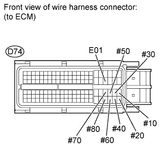 |
Disconnect the D74 ECM connector.
Turn the ignition switch to ON.
Measure the voltage according to the value(s) in the table below.
| Tester Connection | Switch Condition | Specified Condition |
| D74-86 (#10) - D74-43 (E01) | Ignition switch ON | 11 to 14 V |
| D74-109 (#20) - D74-43 (E01) | Ignition switch ON | 11 to 14 V |
| D74-85 (#30) - D74-43 (E01) | Ignition switch ON | 11 to 14 V |
| D74-108 (#40) - D74-43 (E01) | Ignition switch ON | 11 to 14 V |
| D74-84 (#50) - D74-43 (E01) | Ignition switch ON | 11 to 14 V |
| D74-107 (#60) - D74-43 (E01) | Ignition switch ON | 11 to 14 V |
| D74-83 (#70) - D74-43 (E01) | Ignition switch ON | 11 to 14 V |
| D74-106 (#80) - D74-43 (E01) | Ignition switch ON | 11 to 14 V |
|
| ||||
| OK | |
|
| 11.CHECK FUEL INJECTOR OF MISFIRING CYLINDER |
Check the injector injection [whether fuel volume is high or low, and whether injection pattern is poor] .
|
| ||||
| OK | |
|
| 12.CHECK AIR INDUCTION SYSTEM |
Check the air induction system for vacuum leakage .
|
| ||||
| OK | |
|
| 13.CHECK VALVE TIMING |
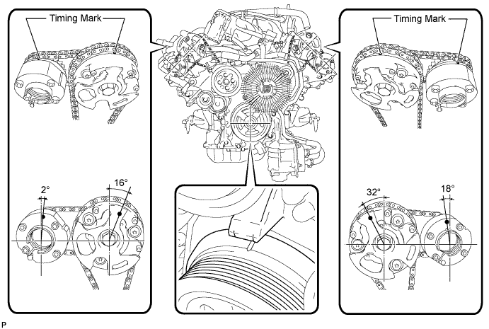
Remove the cylinder head cover LH and RH.
Turn the crankshaft pulley, and align its groove with the timing mark "0" of the timing chain cover.
Check that the timing marks of the camshaft timing gears and camshaft timing exhaust gears are at the positions shown in the illustration.
|
| ||||
| OK | |
|
| 14.CHECK FUEL LEAK |
Check the fuel leak .
|
| ||||
| OK | |
|
| 15.CHECK FUEL PRESSURE SWITCHING SYSTEM |
Check the Fuel Pressure Switching System (Click here).
| NEXT | |
|
| 16.READ VALUE USING TECHSTREAM (COOLANT TEMP) |
Connect the Techstream to the DLC3.
Turn the ignition switch to ON and turn the Techstream ON.
Enter the following menus: Powertrain / Engine and ECT / Data List / All Data / Coolant Temp.
Read the Coolant Temp twice, when the engine is both cold and warmed up.
|
| ||||
| OK | |
|
| 17.READ VALUE USING TECHSTREAM (MAF) |
Connect the Techstream to the DLC3.
Turn the ignition switch to ON.
Turn the Techstream on.
Enter the following menus: Powertrain / Engine and ECT / Data List / All Data / MAF and Coolant Temp.
Allow the engine to idle until the Coolant Temp reaches 75°C (167°F) or more.
Read the MAF with the engine in an idling condition and no load.
|
| ||||
| OK | ||
 | ||
| ||
| 18.CHECK AIR INDUCTION SYSTEM |
Check the air induction system for vacuum leakage .
|
| ||||
| OK | |
|
| 19.CHECK VALVE TIMING |
Remove the cylinder head cover LH and RH.
Turn the crankshaft pulley, and align its groove with the timing mark "0" of the timing chain cover.
Check that the timing marks of the camshaft timing gears and camshaft timing exhaust gears are at the positions shown in the illustration.
|
| ||||
| OK | |
|
| 20.CHECK FUEL LEAK |
Check the fuel leak .
|
| ||||
| OK | |
|
| 21.CHECK FUEL PRESSURE SWITCHING SYSTEM |
Check the Fuel Pressure Switching System (Click here).
| NEXT | |
|
| 22.READ VALUE USING TECHSTREAM (COOLANT TEMP) |
Connect the Techstream to the DLC3.
Turn the ignition switch to ON and turn the Techstream ON.
Enter the following menus: Powertrain / Engine and ECT / Data List / All Data / Coolant Temp.
Read the Coolant Temp twice, when the engine is both cold and warmed up.
|
| ||||
| OK | |
|
| 23.READ VALUE USING TECHSTREAM (MAF) |
Connect the Techstream to the DLC3.
Turn the ignition switch to ON.
Turn the Techstream on.
Enter the following menus: Powertrain / Engine and ECT / Data List / All Data / MAF and Coolant Temp.
Allow the engine to idle until the Coolant Temp reaches 75°C (167°F) or more.
Read the MAF with the engine in an idling condition and no load.
|
| ||||
| OK | |
|
| 24.INSPECT SPARK PLUG |
|
Remove the ignition coil and the spark plug of the misfiring cylinder (Click here).
Measure the spark plug electrode gap.
Check the electrode for carbon deposits.
| Manufacturer | Product |
| DENSO | SK20HR11 |
|
| ||||
| OK | |
|
| 25.CHECK FOR SPARKS AND IGNITION |
|
Disconnect the injector connectors to prevent the engine from starting.
Remove the ignition coil from the cylinder head (Click here).
Install the spark plug onto the ignition coil.
Attach the spark plug assembly to the cylinder head.
Crank the engine for less than 2 seconds and check the spark.
Install the ignition coil.
Reconnect the injector connectors.
|
| ||||
| OK | |
|
| 26.CHECK CYLINDER COMPRESSION PRESSURE |
Measure the cylinder compression pressure of the misfiring cylinder .
|
| ||||
| OK | |
|
| 27.INSPECT ECM TERMINAL OF MISFIRING CYLINDER (#10, #20, #30, #40, #50, #60, #70 AND/OR #80 VOLTAGE) |
|
Disconnect the D74 ECM connector.
Turn the ignition switch to ON.
Measure the voltage according to the value(s) in the table below.
| Tester Connection | Switch Condition | Specified Condition |
| D74-86 (#10) - D74-43 (E01) | Ignition switch ON | 11 to 14 V |
| D74-109 (#20) - D74-43 (E01) | Ignition switch ON | 11 to 14 V |
| D74-85 (#30) - D74-43 (E01) | Ignition switch ON | 11 to 14 V |
| D74-108 (#40) - D74-43 (E01) | Ignition switch ON | 11 to 14 V |
| D74-84 (#50) - D74-43 (E01) | Ignition switch ON | 11 to 14 V |
| D74-107 (#60) - D74-43 (E01) | Ignition switch ON | 11 to 14 V |
| D74-83 (#70) - D74-43 (E01) | Ignition switch ON | 11 to 14 V |
| D74-106 (#80) - D74-43 (E01) | Ignition switch ON | 11 to 14 V |
|
| ||||
| OK | |
|
| 28.CHECK FUEL INJECTOR OF MISFIRING CYLINDER |
Check the injector injection [whether fuel volume is high or low, and whether injection pattern is poor] .
|
| ||||
| OK | ||
| ||
| ||
| 29.CHANGE TO NORMAL SPARK PLUG AND CHECK SPARK OF MISFIRING CYLINDER |
Change the installed spark plug to a spark plug that functions normally.
Perform a spark test.
Install the spark plug to the ignition coil and connect the ignition coil connector.
Disconnect the injector connector.
Ground the spark plug.
Check if sparks occur while the engine is being cranked.
|
| ||||
| OK | ||
| ||
| ||
| 30.CHANGE TO NORMAL IGNITION COIL AND CHECK SPARK OF MISFIRING CYLINDER |
Change the ignition coil to an ignition coil that functions normally.
Perform a spark test.
Install the spark plug to the ignition coil and connect the ignition coil connector.
Disconnect the injector connector.
Ground the spark plug.
Check if sparks occur while the engine is being cranked.
|
| ||||
| OK | ||
| ||
| ||
| 31.CHECK FUEL LEAK |
Check the fuel leak .
|
| ||||
| OK | |
|
| 32.READ VALUE USING TECHSTREAM (MAF) |
Connect the Techstream to the DLC3.
Turn the ignition switch to ON.
Turn the Techstream on.
Enter the following menus: Powertrain / Engine and ECT / Data List / All Data / MAF and Coolant Temp.
Allow the engine to idle until the Coolant Temp reaches 75°C (167°F) or more.
Read the MAF with the engine in an idling condition and no load.
|
| ||||
| OK | |
|
| 33.CHECK AIR INDUCTION SYSTEM |
Check the air induction system for vacuum leakage .
|
| ||||
| OK | |
|
| 34.CHECK FUEL INJECTOR OF MISFIRE CYLINDER |
Check the injector injection [whether fuel volume is high or low, and whether injection pattern is poor] .
|
| ||||
| OK | ||
| ||
| ||

