
DTC 01-DF Master Error |
| DTC No. | DTC Detection Condition | Trouble Area |
| 01-DF* | The device with a display fails and the master is switched to the audio device. Also when a communication error between the sub-master (audio) and master occurs, this code is stored. |
|
| 1.CHECK RADIO RECEIVER POWER SOURCE CIRCUIT |
Refer to the radio receiver power source circuit (Click here).
If the power source circuit is operating normally, proceed to the next step.
| NEXT | |
|
| 2.INSPECT RADIO RECEIVER |
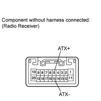 |
Disconnect the K4 receiver connector.
Measure the resistance according to the value(s) in the table below.
| Tester Connection | Condition | Specified Condition |
| K4-5 (ATX+) - K4-15 (ATX-) | Always | 60 to 80 Ω |
| Result | Proceed to |
| OK | A |
| NG (for Column Shift Type) | B |
| NG (for Floor Shift Type) | C |
|
| ||||
|
| ||||
| A | |
|
| 3.IDENTIFY COMPONENT WHICH HAS STORED THIS CODE |
Enter the diagnostic mode.
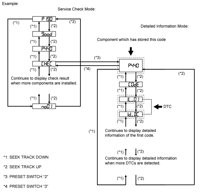
Press the preset switch "3" to change to "Detailed Information Mode".
Identify the component which has stored this code.
| Component | Physical address |
| Stereo component amplifier | 440 |
| "Bluetooth" handsfree module | 19D |
| NEXT | |
|
| 4.CHECK COMPONENT WHICH HAS STORED THIS CODE |
Select the component which has stored this code.
| Component | Proceed to |
| "Bluetooth" handsfree module (for Column Shift Type) | A |
| "Bluetooth" handsfree module (for Floor Shift Type) | B |
| Except "Bluetooth" handsfree module | C |
|
| ||||
|
| ||||
| C | |
|
| 5.CHECK HARNESS AND CONNECTOR (RADIO RECEIVER - COMPONENT WHICH HAS STORED THIS CODE) |
Referring to the AVC-LAN wiring diagram below, check the AVC-LAN circuit between the radio receiver and the component which has stored this code.
Disconnect all connectors between the radio receiver and the component which has stored this code.
Check for an open or short in the AVC-LAN circuit between the radio receiver and the component which has stored this code.
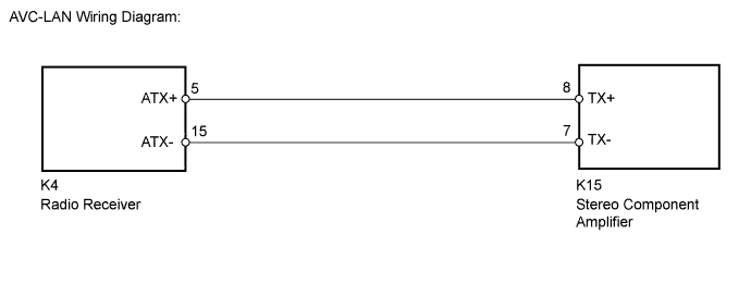
|
| ||||
| OK | |
|
| 6.REPLACE RADIO RECEIVER |
Replace the radio receiver for column shift type (Click here) or floor shift type (Click here).
|
| ||||
| OK | ||
 | ||
| ||
