 |
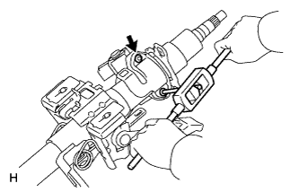
Using a screw extractor, remove the 2 tapered-head bolts, and then remove the upper steering column with switch bracket and the steering lock bracket from the steering column.
IGNITION SWITCH > REMOVAL |
| 1. DISCONNECT CABLE FROM NEGATIVE BATTERY TERMINAL |
| 2. REMOVE STEERING COLUMN ASSEMBLY |
for Manual Tilt:
Remove the steering column (Click here).
for Manual Tilt and Telescopic:
Remove the steering column (Click here).
for Power Tilt and Power Telescopic:
Remove the steering column (Click here).
| 3. REMOVE UPPER STEERING COLUMN WITH SWITCH BRACKET ASSEMBLY (for Manual Tilt) |
Secure the steering column in a vise.
Using a center punch, mark the center of the 2 tapered-head bolts.
Using a 3 to 4 mm (0.119 to 0.159 in.) drill, drill a hole in the 2 tapered-head bolts.
|
Using a screw extractor, remove the 2 tapered-head bolts, and then remove the upper steering column with switch bracket and the steering lock bracket from the steering column.
| 4. REMOVE UPPER STEERING COLUMN WITH SWITCH BRACKET ASSEMBLY (for Manual Tilt and Manual Telescopic Steering Column) |
Secure the steering column in a vise.
Using a center punch, mark the center of the 2 tapered-head bolts.
Using a 3 to 4 mm (0.119 to 0.159 in.) drill, drill a hole in the 2 tapered-head bolts.
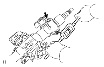 |
Using a screw extractor, remove the 2 tapered-head bolts, and then remove the upper steering column with switch bracket and the steering lock bracket from the steering column.
| 5. REMOVE UPPER STEERING COLUMN WITH SWITCH BRACKET ASSEMBLY (for Power Tilt and Power Telescopic Steering Column) |
Secure the steering column in a vise.
Using a center punch, mark the center of the 2 tapered-head bolts.
Using a 3 to 4 mm (0.119 to 0.159 in.) drill, drill a hole in the 2 tapered-head bolts.
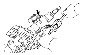 |
Using a screw extractor, remove the 2 tapered-head bolts, and then remove the upper steering column with switch bracket and the steering lock bracket from the steering column.
| 6. REMOVE IGNITION SWITCH ASSEMBLY |
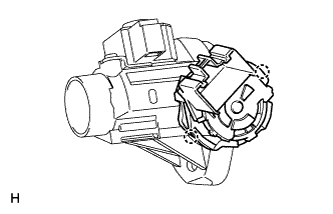 |
Detach the 2 claws and remove the ignition switch from the steering lock.