 |
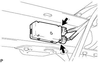
Disconnect the 2 fuel pump ECU connectors.
CYLINDER HEAD GASKET (for Bank 1) > REMOVAL |
| 1. DISCHARGE FUEL SYSTEM PRESSURE |
Disconnect the cable from the negative (-) battery terminal.
|
Disconnect the 2 fuel pump ECU connectors.
Connect the cable to the negative (-) battery terminal.
Start the engine. After the engine has stopped on its own, turn the ignition switch OFF.
Crank the engine again, then check that the engine does not start.
Loosen the fuel tank cap, then discharge the pressure in the fuel tank completely.
Connect the 2 fuel pump ECU connectors.
| 2. DISCONNECT CABLE FROM NEGATIVE BATTERY TERMINAL |
| 3. DRAIN ENGINE OIL |
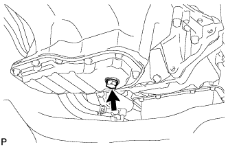 |
Remove the oil filler cap.
Remove the oil drain plug and gasket, and drain the engine oil into a container.
| 4. REMOVE FRONT EXHAUST PIPE ASSEMBLY |
for Regular cab standard deck, refer to the following procedures (Click here).
except Regular cab standard deck, refer to the following procedures (Click here).
| 5. REMOVE WINDSHIELD WIPER MOTOR ASSEMBLY |
Remove the windshield wiper motor (Click here).
| 6. REMOVE COWL TOP OUTER PANEL SUB-ASSEMBLY |
Disconnect the 2 washer hoses.
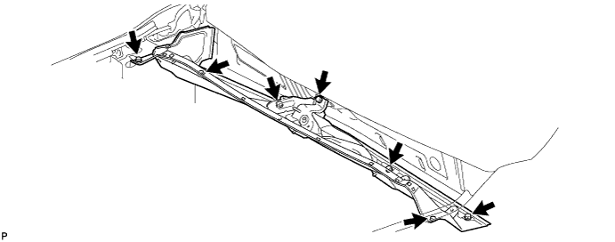
Remove the 7 bolts and outer panel.
| 7. REMOVE TIMING BELT |
Remove the timing belt (Click here).
| 8. DISCONNECT VACUUM HOSE ASSEMBLY |
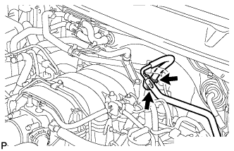 |
Remove the bolt and disconnect the vacuum hose assembly.
| 9. REMOVE NO. 2 WATER BY-PASS PIPE |
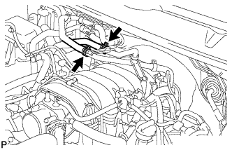 |
Disconnect the 2 water hoses from the No. 2 water by-pass pipe.
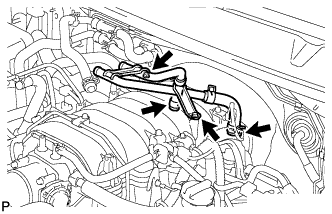 |
Remove the 2 bolts.
Remove No. 2 water by-pass pipe together with the water hose.
| 10. DISCONNECT FUEL MAIN TUBE |
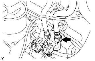 |
Remove the fuel pipe clamp.
Disconnect the fuel main tube (Click here).
| 11. DISCONNECT FUEL RETURN TUBE |
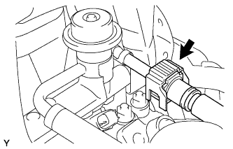 |
Disconnect the fuel return tube (Click here).
| 12. REMOVE FRONT FENDER APRON SEAL LH |
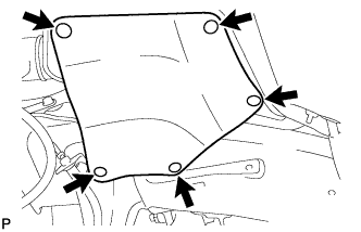 |
Remove the 5 clips and fender apron seal.
| 13. REMOVE NO. 2 AIR HOSE |
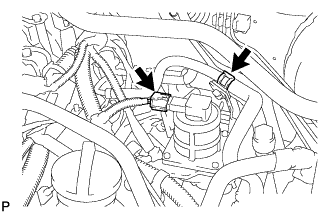 |
Disconnect the air switching valve connector.
Disconnect the fuel hose clamp.
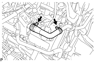 |
Remove the air hose.
| 14. REMOVE NO. 3 AIR TUBE |
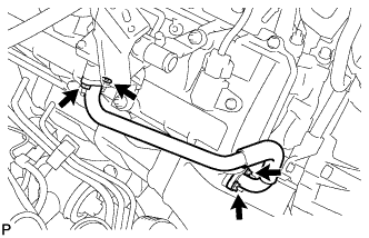 |
Remove the 4 nuts, air tube and 2 gaskets.
| 15. REMOVE AIR SWITCHING VALVE ASSEMBLY (for Bank 1) |
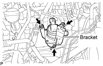 |
Remove the 3 nuts and air switching valve.
| 16. REMOVE INTAKE MANIFOLD |
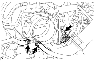 |
Disconnect the throttle position sensor and control motor connector.
Disconnect the 2 water by-pass hoses from the throttle body.
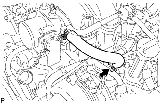 |
Disconnect the No. 1 ventilation hose from the ventilation valve on the LH cylinder head.
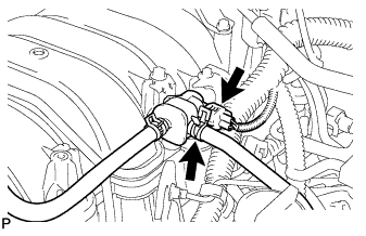 |
Disconnect the purge VSV connector.
Disconnect the purge line hose from the purge VSV.
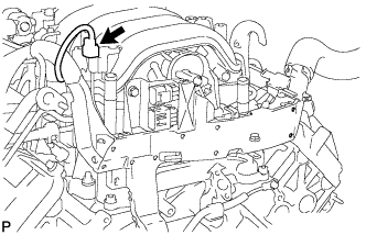 |
Disconnect the VSV connector.
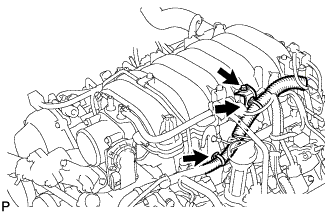 |
Disconnect the 2 wire clamps from the wire bracket and engine hanger.
Remove the bolt and wire bracket from the intake manifold.
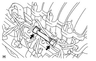 |
Disconnect the 2 wire clamps from the wire clamp bracket on the RH delivery pipe.
Disconnect the 8 injector connectors.
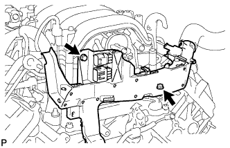 |
Remove the 2 bolts and disconnect the engine wire protector.
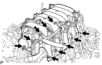 |
Remove the 6 bolts, 4 nuts, intake manifold and 2 gaskets.
| 17. REMOVE WATER INLET HOUSING |
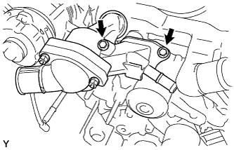 |
Disconnect the water by-pass hose from the water inlet housing.
Remove the 2 bolts holding the water inlet housing to the water pump.
Disconnect the water inlet housing from the front water by-pass joint, and remove the water inlet and inlet housing assembly.
Remove the O-ring from the water inlet housing.
| 18. REMOVE FRONT WATER BY-PASS JOINT |
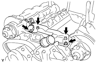 |
Remove the 4 nuts, water by-pass joint and 2 gaskets.
| 19. REMOVE WATER BY-PASS PIPE SUB-ASSEMBLY |
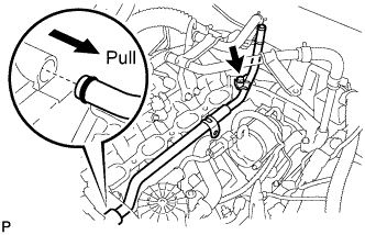 |
Remove the bolt and pull out the water by-pass pipe.
Remove the O-ring from the water by-pass pipe.
| 20. REMOVE REAR WATER BY-PASS JOINT |
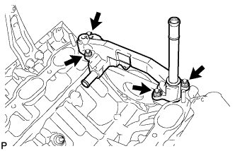 |
Disconnect the air hose and remove the 4 nuts, water by-pass joint and 2 gaskets.
| 21. REMOVE IGNITION COIL ASSEMBLY |
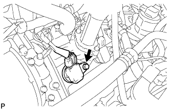 |
Disconnect the 8 ignition coil connectors.
Remove the 8 bolts and pull out the 8 ignition coils.
| 22. REMOVE SPARK PLUG |
| 23. REMOVE CYLINDER HEAD COVER SUB-ASSEMBLY LH |
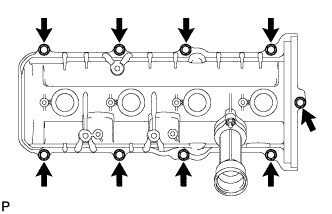 |
Remove the 9 bolts, cylinder head cover and gasket.
| 24. REMOVE CAMSHAFT POSITION SENSOR ASSEMBLY |
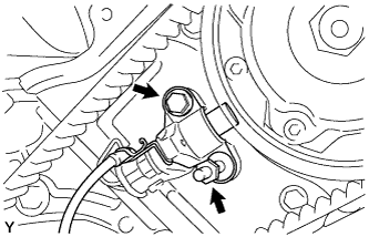 |
Remove the bolt, stud bolt and camshaft position sensor.
| 25. REMOVE CAMSHAFT TIMING PULLEY LH |
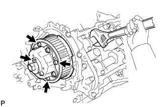 |
Hold the hexagonal portion of the camshaft with a wrench and remove the 4 bolts indicated by the arrows in the illustration and timing pulley.
| 26. REMOVE REAR NO. 1 TIMING BELT PLATE LH |
Remove the 2 bolts, No. 1 timing belt plate and No. 2 timing belt plate.
| 27. REMOVE CAMSHAFT SUB-ASSEMBLY LH |
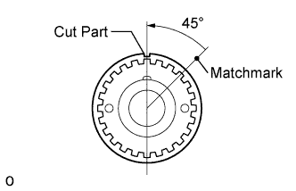 |
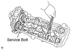 |
Bring the service bolt hole of the sub-gear upward by turning the hexagonal portion of the exhaust camshaft with a wrench.
Secure the sub-gear to the main gear with a service bolt.
| Thread Diameter | Thread Pitch | Bolt Length |
| 6.0 mm | 1.0 mm | 16 to 20 mm (0.630 to 0.787 in.) |
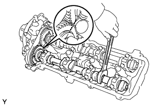 |
Using a wrench, turn the camshaft so that the timing marks (2 dot marks each) on the camshaft drive and driven main gears are aligned, as shown in the illustration.
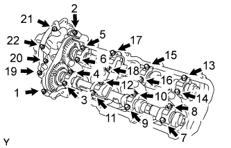 |
Uniformly loosen and remove the 22 bearing cap bolts in several steps, in the order shown in the illustration.
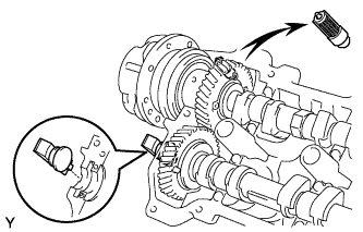 |
Remove the cap bolts, 4 seal washers, oil feed pipe, 9 bearing caps, camshaft housing plug, oil control valve filter and camshafts.
| 28. REMOVE VALVE LIFTER |
Remove the valve lifters and shims from the cylinder head.
| 29. REMOVE CYLINDER HEAD LH |
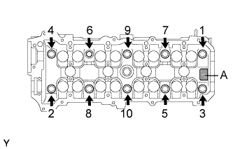 |
Uniformly loosen the 10 cylinder head bolts on the cylinder head in several passes, in the sequence shown in the illustration.
Remove the bolts and plate washers.
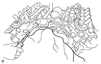 |
Remove the cylinder head by prying between the cylinder block and cylinder head with a screwdriver.
| 30. REMOVE CYLINDER HEAD GASKET LH |
| 31. REMOVE CAMSHAFT TIMING TUBE ASSEMBLY |
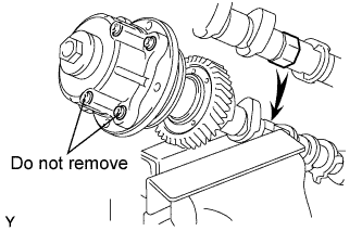 |
Mount the hexagonal portion of the camshaft in a vise.
Remove the screw plug and seal washer.
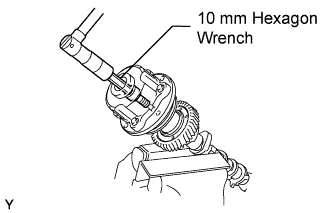 |
Using a 10 mm hexagon wrench, remove the bolt.
Pull out the timing tube and drive gear assembly from the camshaft.
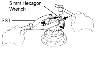 |
Using SST and a 5 mm hexagon wrench, remove the 4 bolts, drive gear and oil seal.