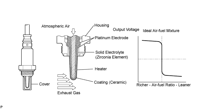
DTC P0136 Oxygen Sensor Circuit Malfunction (Bank 1 Sensor 2) |
DTC P0137 Oxygen Sensor Circuit Low Voltage (Bank 1 Sensor 2) |
DTC P0138 Oxygen Sensor Circuit High Voltage (Bank 1 Sensor 2) |
DTC P0139 Oxygen Sensor Circuit Slow Response (Bank 1 Sensor 2) |
DTC P0156 Oxygen Sensor Circuit Malfunction (Bank 2 Sensor 2) |
DTC P0157 Oxygen Sensor Circuit Low Voltage (Bank 2 Sensor 2) |
DTC P0158 Oxygen Sensor Circuit High Voltage (Bank 2 Sensor 2) |
DTC P0159 Oxygen Sensor Circuit Slow Response (Bank 2 Sensor 2) |
| DTC No. | DTC Detection Condition | Trouble Area |
| P0136 P0156 | Either condition is met:
|
|
| P0137 P0157 | Either condition is met:
|
|
| P0138 P0158 |
|
|
| P0139 P0159 |
|
|
| DTC No. | DTC Detection Condition | Trouble Area |
| P0136 P0156 | Not applicable | None |
| P0137 P0157 | Low voltage (open): During active air-fuel ratio control, following conditions (a) and (b) met for certain period of time (2 trip detection logic)
|
|
| P0138 P0158 | Not applicable | None |
| P0139 P0159 | Not applicable | None |
| Active Air-Fuel Ratio Control |
| Abnormal Voltage Output of Heated Oxygen (HO2) Sensor (DTC P0136 and P0156) |
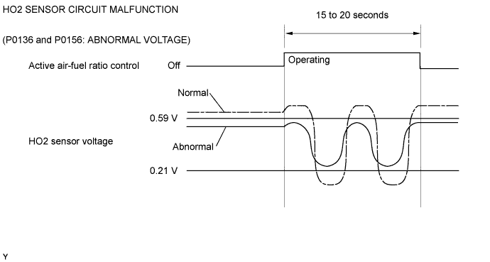
| Open in Heated Oxygen (HO2) Sensor Circuit (DTC P0137 and P0157) |
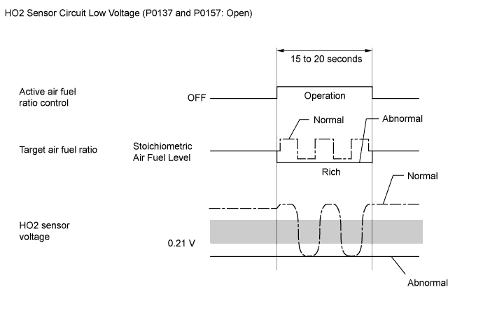
| High or Low Impedance of Heated Oxygen (HO2) Sensor (DTC P0136 and P0156 or P0137 and P0157) |
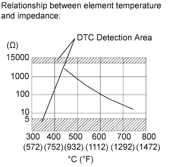 |
| Extremely High Output Voltage of Heated Oxygen (HO2) Sensor (DTC P0138 or P0158) |
| Heated Oxygen Sensor Output Voltage During Fuel Cut (P0139 or P0159) |
| Related DTCs | P0136: Heated oxygen sensor (for Bank 1) output voltage (Abnormal voltage output) P0136: Heated oxygen sensor (for Bank 1) impedance (Low) P0137: Heated oxygen sensor (for Bank 1) output voltage (Low voltage) P0137: Heated oxygen sensor (for Bank 1) impedance (High) P0138: Heated oxygen sensor (for Bank 1) output voltage (Extremely high) P0139: Heated oxygen sensor output voltage during fuel cut (for Bank 1) P0156: Heated oxygen sensor (for Bank 2) output voltage (Abnormal voltage output) P0156: Heated oxygen sensor (for Bank 2) impedance (Low) P0157: Heated oxygen sensor (for Bank 2) output voltage (Low voltage) P0157: Heated oxygen sensor (for Bank 2) impedance (High) P0158: Heated oxygen sensor (for Bank 2) output voltage (Extremely high) P0159: Heated oxygen sensor output voltage during fuel cut (for Bank 2) |
| Required Sensors/Components (Main) | Heated oxygen sensor |
| Required Sensors/Components (Related) | Crankshaft position sensor, engine coolant temperature sensor, mass air flow meter and throttle position sensor |
| Frequency of Operation | Once per driving cycle: Active air-fuel ratio control detection Continuous: Other |
| Duration | 20 seconds: Active air-fuel ratio control detection 90 seconds: Heated oxygen sensor impedance (High) 30 seconds: Heated oxygen sensor impedance (Low) 10 seconds: Output voltage (Extremely high) 7 seconds: Heated oxygen sensor voltage (During fuel cut) |
| MIL Operation | 2 driving cycles |
| Sequence of Operation | None |
| Monitor runs whenever following DTCs not present | P0016, P0018 (VVT system - Misalignment) P0017, P0019 (Exhaust VVT system - Misalignment) P0031, P0032, P0051, P0052, P101D, P103D (Air fuel ratio sensor heater) P0037, P0038, P0057, P0058, P102D, P105D (Rear oxygen sensor heater) P006A, P0107, P0108 (Manifold absolute pressure) P0102, P0103 (Mass air flow meter) P0112, P0113 (Intake air temperature sensor) P0115, P0117, P0118 (Engine coolant temperature sensor) P0120, P0121, P0122, P0123, P0220, P0222, P0223, P2135 (Throttle position sensor) P0125 (Insufficient coolant temperature for closed loop fuel control) P0128 (Thermostat) P014C, P014D, P014E, P014F, P015A, P015B, P015C, P015D, P2195, P2196, P2197, P2198, P2237, P2238, P2239, P2240, P2241, P2242, P2252, P2253, P2255, P2256 (Front oxygen/Air fuel ratio sensor) P0171, P0172, P0174, P0175 (Fuel system) P0301 - P0308 (Misfire) P0335 (Crankshaft position sensor) P0401 (EGR system) P0412, P0415, P0418, P0419, P1613, P1614 (Secondary air injection system control) P0451, P0452, P0453 (EVAP system) P0500, P0722 (Vehicle speed sensor) P1340 (Camshaft position sensor) P2440 - P2447 (Secondary air injection system) |
| Active air-fuel ratio control | Executing |
| Active air-fuel ratio control begins when all of following conditions met: | - |
| Battery voltage | 11 V or more |
| Engine coolant temperature | 75°C (167°F) or more |
| Idling | OFF |
| Engine RPM | Less than 3200 rpm |
| A/F sensor status | Activated |
| Fuel system status | Closed loop |
| Fuel cut | OFF |
| Engine load | 10 to 75% |
| Transmission gear | 4th or higher |
| Battery voltage | 11 V or more |
| Estimated rear HO2 sensor temperature | Less than 700°C (1292°F) |
| ECM monitor | Completed |
| DTC P0607 | Not set |
| Battery voltage | 11 V or more |
| Estimated rear HO2 sensor temperature | 450 to 750°C (842 to 1382°F) |
| ECM monitor | Completed |
| DTC P0607 | Not set |
| Battery voltage | 11 V or more |
| Time after engine start | 2 seconds or more |
| Engine coolant temperature | 75°C (167°F) or higher |
| Estimated catalyst temperature | 400°C (752°F) or higher |
| Fuel cut | ON |
| All of following conditions (a), (b) and (c) met | - |
| (a) Commanded air-fuel ratio | 14.3 or less |
| (b) Rear HO2 sensor voltage | 0.21 to 0.59 V |
| (c) OSC (Oxygen Storage Capacity of Catalyst) | 2 g or more |
| All of following conditions (a), (b) and (c) met | - |
| (a) Commanded air-fuel ratio | 14.3 or less |
| (b) Rear HO2 sensor voltage | Less than 0.21 V |
| (c) OSC | 2 g or more |
| Duration following condition met | 30 seconds or more |
| Heated oxygen sensor impedance | Less than 5 Ω |
| Duration following condition met | 30 seconds or more |
| Heated oxygen sensor impedance | 15 kΩ or more |
| Duration following condition met | 10 seconds or more |
| Heated oxygen sensor voltage | 1.2 V or more |
| Either condition is met | - |
| Total airflow volume reached after start of fuel-cut while heated oxygen sensor voltage remains at 0.2 V or higher | More than 15.3 g |
| Duration that rear oxygen sensor voltage to drop from 0.35 V to 0.2 V during fuel-cut | 1 second or more |
| Duration following condition met | 30 seconds or more |
| Heated oxygen sensor voltage | Varies between 0.1 and 0.9 V |
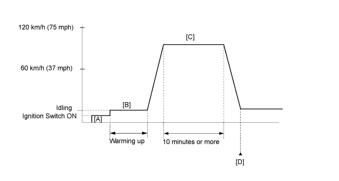
| Techstream Display | Description |
| NORMAL |
|
| ABNORMAL |
|
| INCOMPLETE |
|
| N/A |
|
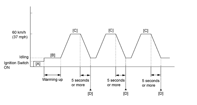
| Techstream Display | Description |
| NORMAL |
|
| ABNORMAL |
|
| INCOMPLETE |
|
| N/A |
|
| Techstream Display (Sensor) | Injection Volume | Status | Voltage |
| AFS Voltage B1S1 or AFS Voltage B2S1 (A/F) | +12.5% | Rich | Below 3.1 V |
| AFS Voltage B1S1 or AFS Voltage B2S1 (A/F) | -12.5% | Lean | Higher than 3.4 V |
| O2S B1S2 or O2S B2S2 (HO2) | +12.5% | Rich | Higher than 0.55 V |
| O2S B1S2 or O2S B2S2 (HO2) | -12.5% | Lean | Below 0.4 V |
| Case | A/F Sensor (Sensor 1) Output Voltage | HO2 Sensor (Sensor 2) Output Voltage | Main Suspected Trouble Area |
| 1 |   |  | - |
| 2 |  | |
|
| 3 | | |
|
| 4 | | |
|
| 1.READ OUTPUT DTC |
Connect the Techstream to the DLC3.
Turn the ignition switch to ON.
Turn the Techstream on.
Enter the following menus: Powertrain / Engine and ECT / Trouble Codes.
Read DTCs.
| Result | Proceed to |
| P0138 or P0158 is output | A |
| P0137 or P0157 is output | B |
| P0136 or P0156 is output | C |
| P0139 or P0159 is output | D |
| P0136, P0137, P0138, P0139, P0156, P0157, P0158 or P0159 and other DTCs are output | E |
|
| ||||
|
| ||||
|
| ||||
|
| ||||
| A | |
 |
| 2.INSPECT HEATED OXYGEN SENSOR (CHECK FOR SHORT) |
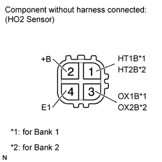 |
Disconnect the HO2 sensor connector.
Measure the resistance according to the value(s) in the table below.
| Tester Connection | Condition | Specified Condition |
| 2 (+B) - 3 (OX1B) | Always | 10 kΩ or higher |
| 2 (+B) - 3 (OX2B) | Always | 10 kΩ or higher |
| 2 (+B) - 4 (E1) | Always | 10 kΩ or higher |
|
| ||||
| OK | |
|
| 3.CHECK HARNESS AND CONNECTOR (CHECK FOR SHORT) |
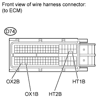 |
Turn the ignition switch off and wait for 5 minutes.
Disconnect the ECM connector.
Measure the resistance according to the value(s) in the table below.
| Tester Connection | Condition | Specified Condition |
| D74-45 (HT1B) - D74-114 (OX1B) | Always | 10 kΩ or higher |
| D74-44 (HT2B) - D74-112 (OX2B) | Always | 10 kΩ or higher |
|
| ||||
| OK | ||
 | ||
| ||
| 4.PERFORM ACTIVE TEST USING TECHSTREAM (CONTROL THE INJECTION VOLUME FOR A/F SENSOR) |
Connect the Techstream to the DLC3.
Start the engine.
Turn the Techstream on.
Warm up the engine.
Enter the following menus: Powertrain / Engine and ECT / Active Test / Control the Injection Volume for A/F Sensor / All Data / O2S B1S2 or O2S B2S2.
Change the fuel injection volume using the Techstream, monitoring the voltage output of the HO2 sensors displayed on the Techstream.
|
| ||||
| OK | |
|
| 5.PERFORM ACTIVE TEST USING TECHSTREAM (INJECTION VOLUME FOR A/F SENSOR) |
Connect the Techstream to the DLC3.
Turn the Techstream on.
Start the engine.
Warm up the engine.
Enter the following menus: Powertrain / Engine and ECT / Active Test / Control the Injection Volume for A/F Sensor.
Change the fuel injection volume using the Techstream, and monitor the voltage output of the Air-Fuel Ratio (A/F) and HO2 sensors displayed on the Techstream.
| Techstream Display (Sensor) | Voltage Variation | Proceed to |
| AFS Voltage B1S1 AFS Voltage B2S1 | Alternates between more and less than 3.3 V | OK |
| Remains at more than 3.3 V | NG | |
| Remains at less than 3.3 V | NG |
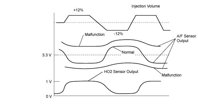
|
| ||||
| OK | |
|
| 6.PERFORM ACTIVE TEST USING TECHSTREAM (CONTROL THE EGR STEP POSITION) |
Connect the Techstream to the DLC3.
Start the engine and warm it up until the engine coolant temperature reaches 75°C (167°F) or higher.
Turn the Techstream on.
Enter the following menus: Powertrain / Engine and ECT / Active Test / Control the EGR Step Position.
Confirm the Throttle Idle Position is ON and check the engine idling condition and MAP values in the Data List while performing the Active Test.
| - | EGR Step Position (Active Test) | |
| 0 Steps | 0 to 30 Steps | |
| Idling condition | Steady idling | Idling changes from steady to rough idling or engine stall |
| MAP (Data List) | 20 to 40 kPa (150 to 300 mmHg) | MAP value is at least +10 kPa (75 mmHg) higher than when EGR valve is fully closed |
|
| ||||
| OK | ||
| ||
| ||
| 7.INSPECT EGR VALVE |
Remove the EGR valve assembly (Click here).
Check if the EGR valve is stuck open.
|
| ||||
| OK | ||
| ||
| ||
| 8.CHECK FOR EXHAUST GAS LEAK |
Check for exhaust gas leak.
|
| ||||
| OK | |
|
| 9.INSPECT HEATED OXYGEN SENSOR (HEATER RESISTANCE) |
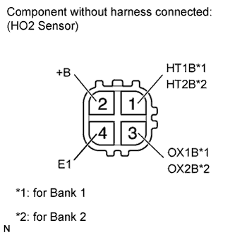 |
Disconnect the HO2 sensor connector.
Measure the resistance according to the value(s) in the table below.
| Tester Connection | Condition | Specified Condition |
| 1 (HT1B) - 2 (+B) | 20°C (68°F) | 11 to 16 Ω |
| 1 (HT1B) - 4 (E1) | Always | 10 kΩ or higher |
| 1 (HT2B) - 2 (+B) | 20°C (68°F) | 11 to 16 Ω |
| 1 (HT2B) - 4 (E1) | Always | 10 kΩ or higher |
|
| ||||
| OK | |
|
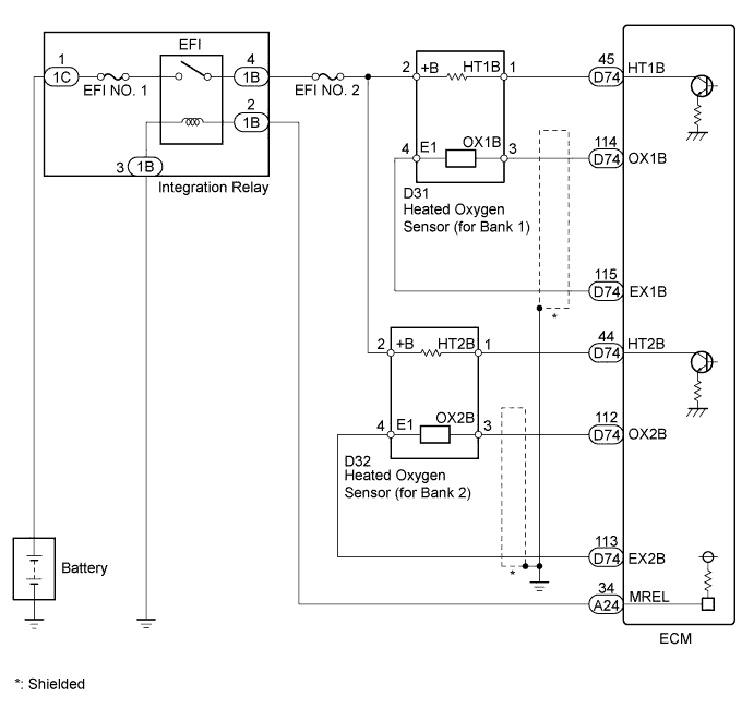
| 10.CHECK HARNESS AND CONNECTOR (HEATED OXYGEN SENSOR - ECM) |
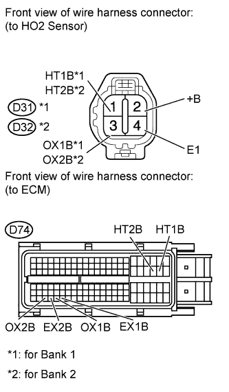 |
Disconnect the HO2 sensor connector.
Disconnect the ECM connector.
Measure the resistance according to the value(s) in the table below.
| Tester Connection | Condition | Specified Condition |
| D31-1 (HT1B) - D74-45 (HT1B) | Always | Below 1 Ω |
| D31-3 (OX1B) - D74-114 (OX1B) | Always | Below 1 Ω |
| D31-4 (E1) - D74-115 (EX1B) | Always | Below 1 Ω |
| D32-1 (HT2B) - D74-44 (HT2B) | Always | Below 1 Ω |
| D32-3 (OX2B) - D74-112 (OX2B) | Always | Below 1 Ω |
| D32-4 (E1) - D74-113 (EX2B) | Always | Below 1 Ω |
| D31-1 (HT1B) or D74-45 (HT1B) - Body ground | Always | 10 kΩ or higher |
| D31-3 (OX1B) or D74-114 (OX1B) - Body ground | Always | 10 kΩ or higher |
| D32-1 (HT2B) or D74-44 (HT2B) - Body ground | Always | 10 kΩ or higher |
| D32-3 (OX2B) or D74-112 (OX2B) - Body ground | Always | 10 kΩ or higher |
|
| ||||
| OK | |
|
| 11.REPLACE HEATED OXYGEN SENSOR |
Replace the heated oxygen sensor (Click here).
| NEXT | |
|
| 12.PERFORM CONFIRMATION DRIVING PATTERN |
Perform the Confirmation Driving Pattern (P0136, P0137, P0138, P0156, P0157 and P0158).
| NEXT | |
|
| 13.CHECK WHETHER DTC OUTPUT RECURS (DTC P0136, P0137, P0138, P0156, P0157 OR P0158 IS OUTPUT AGAIN) |
Connect the Techstream to the DLC3.
Turn the Techstream ON.
Enter the following menus: Powertrain / Engine and ECT / Utility / All Readiness.
Input DTCs: P0136, P0137, P0138, P0156, P0157 and P0158.
Check that the DTC monitor is NORMAL. If the DTC monitor is INCOMPLETE, perform the drive pattern increasing the vehicle speed.
| Result | Proceed to |
| ABNORMAL (DTC P0136, P0137, P0138, P0156, P0157 or P0158 is output) | A |
| NORMAL (DTC is not output) | B |
|
| ||||
| A | |
|
| 14.PERFORM ACTIVE TEST USING TECHSTREAM (CONTROL THE EGR STEP POSITION) |
Connect the Techstream to the DLC3.
Start the engine and warm it up until the engine coolant temperature reaches 75°C (167°F) or higher.
Turn the Techstream on.
Enter the following menus: Powertrain / Engine and ECT / Active Test / Control the EGR Step Position.
Confirm the Throttle Idle Position is ON and check the engine idling condition and MAP values in the Data List while performing the Active Test.
| - | EGR Step Position (Active Test) | |
| 0 Steps | 0 to 30 Steps | |
| Idling condition | Steady idling | Idling changes from steady to rough idling or engine stall |
| MAP (Data List) | 20 to 40 kPa (150 to 300 mmHg) | MAP value is at least +10 kPa (75 mmHg) higher than when EGR valve is fully closed |
|
| ||||
| OK | ||
| ||
| ||
| 15.INSPECT EGR VALVE |
Remove the EGR valve assembly (Click here).
Check if the EGR valve is stuck open.
|
| ||||
| OK | ||
| ||
| ||
| 16.REPLACE AIR FUEL RATIO SENSOR |
Replace the air fuel ratio sensor (Click here).
| NEXT | |
|
| 17.PERFORM CONFIRMATION DRIVING PATTERN |
Perform the Confirmation Driving Pattern (P0136, P0137, P0138, P0156, P0157 and P0158).
| NEXT | |
|
| 18.CHECK WHETHER DTC OUTPUT RECURS (DTC P0136, P0137, P0138, P0156, P0157 OR P0158 IS OUTPUT AGAIN) |
Connect the Techstream to the DLC3.
Turn the Techstream ON.
Enter the following menus: Powertrain / Engine and ECT / Utility / All Readiness.
Input DTCs: P0136, P0137, P0138, P0156, P0157 and P0158.
Check that the DTC monitor is NORMAL. If the DTC monitor is INCOMPLETE, perform the drive pattern increasing the vehicle speed.
| Result | Proceed to |
| ABNORMAL (DTC P0136, P0137, P0138, P0156, P0157 or P0158 is output) | A |
| NORMAL (DTC is not output) | B |
|
| ||||
| A | |
|
| 19.PERFORM ACTIVE TEST USING TECHSTREAM (CONTROL THE EGR STEP POSITION) |
Connect the Techstream to the DLC3.
Start the engine and warm it up until the engine coolant temperature reaches 75°C (167°F) or higher.
Turn the Techstream on.
Enter the following menus: Powertrain / Engine and ECT / Active Test / Control the EGR Step Position.
Confirm the Throttle Idle Position is ON and check the engine idling condition and MAP values in the Data List while performing the Active Test.
| - | EGR Step Position (Active Test) | |
| 0 Steps | 0 to 30 Steps | |
| Idling condition | Steady idling | Idling changes from steady to rough idling or engine stall |
| MAP (Data List) | 20 to 40 kPa (150 to 300 mmHg) | MAP value is at least +10 kPa (75 mmHg) higher than when EGR valve is fully closed |
|
| ||||
| OK | ||
| ||
| ||
| 20.INSPECT EGR VALVE |
Remove the EGR valve assembly (Click here).
Check if the EGR valve is stuck open.
|
| ||||
| OK | ||
| ||
| ||
| 21.CHECK FOR EXHAUST GAS LEAK |
Check for exhaust gas leak.
|
| ||||
| OK | |
|
| 22.CHECK HARNESS AND CONNECTOR (CHECK FOR SHORT) |
|
Turn the ignition switch off and wait for 5 minutes.
Disconnect the ECM connector.
Measure the resistance according to the value(s) in the table below.
| Tester Connection | Condition | Specified Condition |
| D74-45 (HT1B) - D74-114 (OX1B) | Always | 10 kΩ or higher |
| D74-44 (HT2B) - D74-112 (OX2B) | Always | 10 kΩ or higher |
|
| ||||
| OK | |
|
| 23.PERFORM CONFIRMATION DRIVING PATTERN |
Perform the Confirmation Driving Pattern (P0139 and P0159).
| NEXT | |
|
| 24.READ DTC OUTPUT (DTC P0139 OR P0159 IS OUTPUT AGAIN) |
Connect the Techstream to the DLC3.
Turn the Techstream ON.
Enter the following menus: Powertrain / Engine and ECT / Utility / All Readiness.
Input DTCs: P0139 and P0159.
Check that the DTC monitor is NORMAL. If the DTC monitor is INCOMPLETE, perform the drive pattern increasing the vehicle speed.
| Result | Proceed to |
| ABNORMAL (DTC P0139 or P0159 is output) | A |
| NORMAL (DTC is not output) | B |
|
| ||||
| A | |
|
| 25.PERFORM ACTIVE TEST USING TECHSTREAM (CONTROL THE EGR STEP POSITION) |
Connect the Techstream to the DLC3.
Start the engine and warm it up until the engine coolant temperature reaches 75°C (167°F) or higher.
Turn the Techstream on.
Enter the following menus: Powertrain / Engine and ECT / Active Test / Control the EGR Step Position.
Confirm the Throttle Idle Position is ON and check the engine idling condition and MAP values in the Data List while performing the Active Test.
| - | EGR Step Position (Active Test) | |
| 0 Steps | 0 to 30 Steps | |
| Idling condition | Steady idling | Idling changes from steady to rough idling or engine stall |
| MAP (Data List) | 20 to 40 kPa (150 to 300 mmHg) | MAP value is at least +10 kPa (75 mmHg) higher than when EGR valve is fully closed |
|
| ||||
| OK | ||
| ||
| ||
| 26.INSPECT EGR VALVE |
Remove the EGR valve assembly (Click here).
Check if the EGR valve is stuck open.
|
| ||||
| OK | ||
| ||
| ||

