Home › ENGINE ยท 1GR-FE › FUEL › FUEL TANK

FUEL TANK > REMOVAL

for Preparation Click here


1. DISCHARGE FUEL SYSTEM PRESSURE
(Click here)


2. PRECAUTION

NOTICE:
After turning the ignition switch off, waiting time may be required before disconnecting the cable from the battery terminal. Therefore, make sure to read the disconnecting the cable from the battery terminal notice before proceeding with work (Click here).


3. DISCONNECT CABLE FROM NEGATIVE BATTERY TERMINAL

NOTICE:
When disconnecting the cable, some systems need to be initialized after the cable is reconnected (Click here).


4. REMOVE FUEL TANK CAP


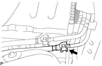
5. DISCONNECT FUEL TANK MAIN TUBE SUB-ASSEMBLY


A239753
  1. Disconnect the fuel tank main tube sub-assembly (Click here).


6. DISCONNECT FUEL TANK RETURN TUBE


A239754
  1. Disconnect the fuel tank return tube (Click here).


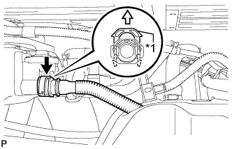
7. DISCONNECT VENT LINE HOSE


    A239757E01
  1. Pull up the retainer and disconnect the vent line hose.
    Text in Illustration 
    *1
    Retainer
    V100136
    Pull Up

    NOTICE:
    1. Do not use any tools in this procedure.
    1. Check for any dirt and foreign matter contamination in the valve and around the connector. Clean if necessary. Foreign matter may damage the O-rings or cause leaks in the seal between the valve and connector.


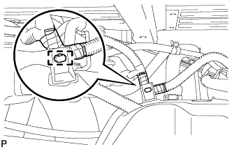
8. DISCONNECT WIRE HARNESS


    A239755
  1. Detach the harness clamp from the fuel tank assembly.


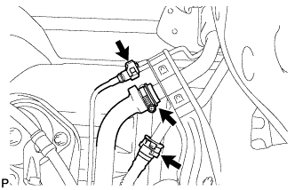
9. DISCONNECT FUEL TANK TO FILLER PIPE HOSE


A239756
  1. Disconnect the fuel tank breather tube (Click here).

  1. Disconnect the fuel tank to filler pipe hose from the fuel tank inlet pipe sub-assembly.

  1. Detach the fuel tank to filler pipe hose and fuel tank breather tube from the No. 1 breather tube clamp.


10. DISCONNECT NO. 1 CANISTER OUTLET HOSE
  1. Disconnect the No. 1 canister outlet hose from the fuel tank inlet pipe sub-assembly.

  1. Detach the fuel tank to filler pipe hose from the No. 1 breather tube clamp.


11. REMOVE FUEL TANK ASSEMBLY
  1. Set a engine lifter underneath the fuel tank assembly.
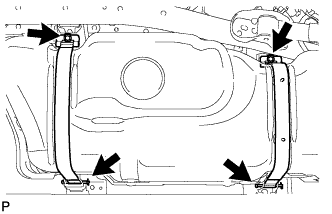


    A152248
  1. Remove the 2 bolts, 2 clips, 2 pins, No. 1 fuel tank band sub-assembly and No. 2 fuel tank band sub-assembly.

  1. Slowly lower the engine lifter slightly.
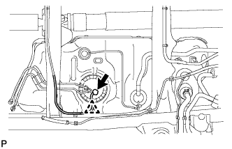
    NOTICE:
    Be careful not to cut the wiring.


    A152243
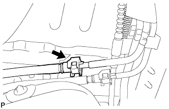
  1. Detach the wire harness clamp from the fuel tank assembly as shown in the illustration.

  1. Disconnect the fuel pump connector and lower the engine lifter.

    NOTICE:
    1. Before this procedure, check the connector for dirt, mud or other contamination.
    2. Do not use any tools in this procedure.


12. REMOVE FUEL TANK INLET PIPE SUB-ASSEMBLY


    A156396
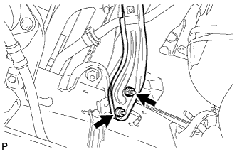
  1. Remove the 2 nuts and fuel tank inlet pipe sub-assembly.


13. REMOVE NO. 1 FUEL TANK HEAT INSULATOR


    A152249E02
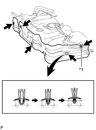
  1. Remove the nut from the No. 1 fuel tank heat insulator.
    Text in Illustration 
    *1
    Nut

  1. Using needle-nose pliers, remove the 4 clips shown in the illustration and then remove the No. 1 fuel tank heat insulator.


14. REMOVE FUEL TANK TO FILLER PIPE HOSE


    A152251
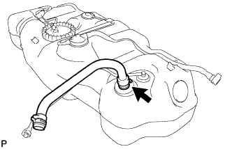
  1. Remove the fuel tank to filler pipe hose from the fuel tank assembly.


15. REMOVE FUEL SUCTION WITH PUMP AND GAUGE TUBE ASSEMBLY


    A152246E02
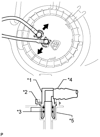
  1. Remove the 2 tube joint clips and pull out the fuel tank return tube and fuel tank main tube sub-assembly.

    NOTICE:
    1. Remove any dirt and foreign matter on the fuel tube joint before performing this work.
    2. Do not allow any scratches or foreign matter on the parts when disconnecting them, as the fuel tube joint contains the O-rings that seal the plug.
    3. Perform this work by hand. Do not use any tools.
    4. Do not forcibly bend, twist or turn the nylon tube.
    5. Protect the disconnected part by covering it with a plastic bag and tape after disconnecting the fuel tank tubes.

    Text in Illustration 
    *1
    Tube Joint
    *2
    Tube Joint Clip
    *3
    O-Ring
    *4
    Fuel Tank Tube
    *5
    Fuel Suction Plate


    A259583E01
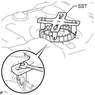
  1. Set SST on the retainer.

    SST
    09808-14030  

    HINT:
    1. Securely attach the claws of SST to the protrusion of the retainer and fix SST in place.
    2. Install SST while pressing the claws of SST against the retainer (towards the center of SST).


    A259580E01
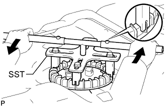
  1. Using SST, loosen the retainer.

    SST
    09808-14030  

    NOTICE:
    1. Do not use any tools other than those specified in this operation. Damage to the retainer or the fuel tank assembly may result.
    2. While pressing down on SST so that the claws of SST do not slip off the protrusion of the retainer, turn the retainer counterclockwise to loosen it.

    HINT:
    The protrusion of the retainer fit in the ends of SST.

  1. Remove the retainer.

  1. Remove the fuel suction with pump and gauge tube assembly from the fuel tank assembly.

    NOTICE:
    Be careful not to bend the arm of the fuel sender gauge.

  1. Remove the gasket from the fuel tank assembly.