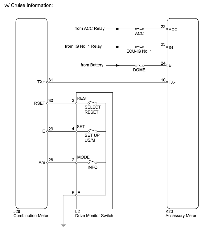
METER / GAUGE SYSTEM > Accessory Meter does not Illuminate |
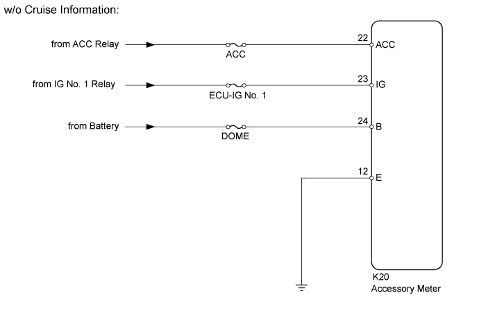
| 1.CHECK ACCESSORY METER ASSEMBLY |
Check the malfunction of the accessory meter.
| Result | Proceed to |
| Accessory meter does not display at all | A |
| Cruise information display does not change (w/ Cruise Information) | B |
|
| ||||
| A | |
 |
| 2.INSPECT FUSE (DOME, ECU-IG NO. 1, ACC) |
Remove the DOME fuse from the engine room junction block.
Remove the ECU-IG No. 1 and ACC fuses from the main body ECU.
Measure the resistance according to the value(s) in the table below.
| Tester Connection | Condition | Specified Condition |
| DOME fuse | Always | Below 1 Ω |
| ECU-IG No. 1 fuse | ||
| ACC fuse |
|
| ||||
| OK | |
|
| 3.CHECK HARNESS AND CONNECTOR (ACCESSORY METER - BATTERY AND BODY GROUND) |
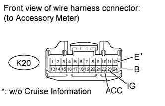 |
Disconnect the K20 accessory meter connector.
Measure the voltage according to the value(s) in the table below.
| Tester Connection | Switch Condition | Specified Condition |
| K20-24 (B) - Body ground | Always | 11 to 14 V |
| K20-23 (IG) - Body ground | Ignition switch ON | 11 to 14 V |
| K20-22 (ACC) - Body ground | Ignition switch ACC | 11 to 14 V |
w/o Cruise Information
Measure the resistance according to the value(s) in the table below.
| Tester Connection | Condition | Specified Condition |
| K20-12 (E) - Body ground | Always | Below 1 Ω |
|
| ||||
| OK | |
|
| 4.REPLACE ACCESSORY METER ASSEMBLY |
Temporarily replace the accessory meter with a new or normally functioning one (Click here).
| NEXT | |
|
| 5.CHECK ACCESSORY METER ASSEMBLY (OPERATION) |
Check that the accessory meter operation is normal.
|
| ||||
| OK | ||
 | ||
| ||
| 6.INSPECT DRIVE MONITOR SWITCH |
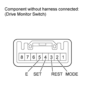 |
Remove the drive monitor switch (Click here).
Measure the resistance according to the value(s) in the table below.
| Tester Connection | Switch Condition | Specified Condition |
| 2 (MODE) - 5 (E) | INFO switch pressed | Below 1 Ω |
| INFO switch not pressed | 10 kΩ or higher | |
| 4 (SET) - 5 (E) | SETUP switch pressed | Below 1 Ω |
| SETUP switch not pressed | 10 kΩ or higher | |
| 3 (REST) - 5 (E) | SELECT switch pressed | Below 1 Ω |
| SELECT switch not pressed | 10 kΩ or higher |
|
| ||||
| OK | |
|
| 7.CHECK HARNESS AND CONNECTOR (COMBINATION METER - DRIVE MONITOR SWITCH AND BODY GROUND) |
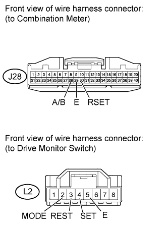 |
Disconnect the J28 combination meter connector.
Disconnect the L2 drive monitor switch connector.
Measure the resistance according to the value(s) in the table below.
| Tester Connection | Condition | Specified Condition |
| J28-28 (A/B) - L2-2 (MODE) | Always | Below 1 Ω |
| J28-29 (E) - L2-4 (SET) | ||
| J28-30 (RSET) - L2-3 (REST) | ||
| L2-5 (E) - Body ground | ||
| J28-28 (A/B) - Body ground | Always | 10 kΩ or higher |
| J28-29 (E) - Body ground | ||
| J28-30 (RSET) - Body ground |
|
| ||||
| OK | |
|
| 8.CHECK HARNESS AND CONNECTOR (COMBINATION METER - ACCESSORY METER) |
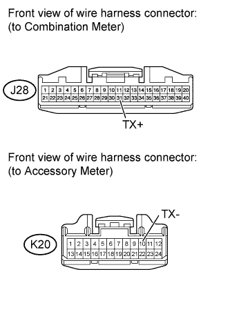 |
Disconnect the J28 combination meter connector.
Disconnect the K20 accessory meter connector.
Measure the resistance according to the value(s) in the table below.
| Tester Connection | Condition | Specified Condition |
| J28-31 (TX+) - K20-10 (TX-) | Always | Below 1 Ω |
| J28-31 (TX+) - Body ground | Always | 10 kΩ or higher |
|
| ||||
| OK | |
|
| 9.REPLACE ACCESSORY METER ASSEMBLY |
Temporarily replace the accessory meter with a new or normally functioning one (Click here).
| NEXT | |
|
| 10.CHECK ACCESSORY METER ASSEMBLY (OPERATION) |
Check that the accessory meter operation is normal.
|
| ||||
| OK | ||
| ||
| ||

