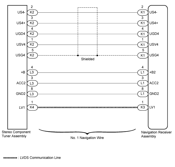
DTC B1532 LVDS Signal Malfunction (from Extension Module) |
DTC B156C Extension Module Disconnected |
| DTC Code | DTC Detection Condition | Trouble Area |
| B1532 | When either condition below is met:
|
|
| B156C |
| 1.CHECK FOR DTC |
Clear the DTCs (Click here).
Check for DTCs (Click here).
|
| ||||
| OK | ||
 | ||
| ||
| 2.CHECK HARNESS AND CONNECTOR (NAVIGATION RECEIVER ASSEMBLY - STEREO COMPONENT TUNER ASSEMBLY) |
Disconnect the K1 and L1 navigation receiver assembly connectors.
Disconnect the K2 and L3 stereo component tuner assembly connector.
Measure the resistance according to the value(s) in the table below.
| Tester Connection | Condition | Specified Condition |
| K1-1 (USV4) - K2-1 (USV4) | Always | Below 1 Ω |
| K1-2 (US4-) - K2-2 (US4-) | Always | Below 1 Ω |
| K1-3 (US4+) - K2-3 (US4+) | Always | Below 1 Ω |
| K1-4 (UGD4) - K2-4 (UGD4) | Always | Below 1 Ω |
| K1-5 (USG4) - K2-5 (USG4) | Always | Below 1 Ω |
| L1-4 (+B2) - L3-4 (+B) | Always | Below 1 Ω |
| L1-3 (ACC2) - L3-3 (ACC2) | Always | Below 1 Ω |
| L1-8 (GND2) - L3-8 (GND2) | Always | Below 1 Ω |
| K1-1 (USV4) - Body ground | Always | 10 kΩ or higher |
| K1-2 (US4-) - Body ground | Always | 10 kΩ or higher |
| K1-3 (US4+) - Body ground | Always | 10 kΩ or higher |
| K1-4 (UGD4) - Body ground | Always | 10 kΩ or higher |
| K1-5 (USG4) - Body ground | Always | 10 kΩ or higher |
| L1-4 (+B2) - Body ground | Always | 10 kΩ or higher |
| L1-3 (ACC2) - Body ground | Always | 10 kΩ or higher |
| L1-8 (GND2) - Body ground | Always | 10 kΩ or higher |
|
| ||||
| OK | |
 |
| 3.CHECK NO. 1 NAVIGATION WIRE |
Replace the No. 1 navigation wire with a known good one.
for Column Shift Type: Click here
for Floor Shift Type: Click here
Clear the DTCs (Click here).
Check for DTCs (Click here).
|
| ||||
| OK | ||
| ||
| ||
| 4.CHECK STEREO COMPONENT TUNER ASSEMBLY |
Replace the stereo component tuner assembly with a known good one.
for Column Shift Type: Click here
for Floor Shift Type: Click here
Clear the DTCs (Click here).
Check for DTCs (Click here).
| Result | Proceed to |
| OK | A |
| NG (for Column Shift Type) | B |
| NG (for Floor Shift Type) | C |
|
| ||||
|
| ||||
| A | ||
| ||
| ||

