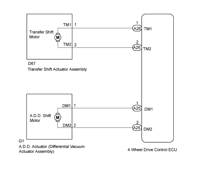
TOUCH SELECT 2-4 AND HIGH-LOW SYSTEM > Shift Motor Circuit |
| 1.CONFIRM PROBLEM SYMPTOM |
Confirm the problem symptoms.
| Result | Proceed to |
| The 4HI indicator light is blinking* | A |
| The 4LO indicator light is blinking* | B |
|
| ||||
| A | |
 |
| 2.CHECK A.D.D. POSITION |
Move the shift lever to N.
Turn the transfer position switch from 2WD to 4H.
Lift up the vehicle until the 2 front wheels or all four wheels are off the ground.
Release the parking brake.
Rotate the rear propeller shaft and check that the front propeller shaft rotates.
| Result | Proceed to |
| The front propeller shaft rotates | A |
| The front propeller shaft does not rotate | B |
|
| ||||
| A | ||
 | ||
| ||
| 3.CHECK TRANSFER SHIFT ACTUATOR ASSEMBLY (TRANSFER SHIFT MOTOR) |
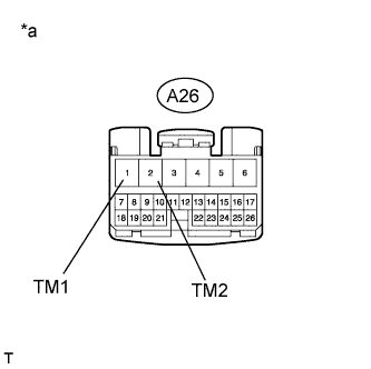 |
Disconnect the 4 wheel drive control ECU connector.
Measure the resistance according to the value(s) in the table below.
| Tester Connection | Condition | Specified Condition |
| A26-1 (TM1) - A26-2 (TM2) | Always | 1 Ω or higher |
| *a | Front view of wire harness connector (to 4 Wheel Drive Control ECU) |
| Result | Proceed to |
| OK | A |
| NG (when 4HI indicator light is blinking*) | B |
| NG (when 4LO indicator light is blinking*) | C |
|
| ||||
|
| ||||
| A | |
|
| 4.CHECK HARNESS AND CONNECTOR (4 WHEEL DRIVE CONTROL ECU - TRANSFER SHIFT ACTUATOR ASSEMBLY) |
Disconnect the A26 4 wheel drive control ECU connector.
Disconnect the D67 transfer shift actuator assembly connector.
Measure the resistance according to the value(s) in the table below.
| Tester Connection | Condition | Specified Condition |
| A26-1 (TM1) or D67-1 (TM1) - A26-2 (TM2) or D67-2 (TM2) | Always | 10 kΩ or higher |
|
| ||||
| OK | ||
| ||
| ||
| 5.CHECK DIFFERENTIAL VACUUM ACTUATOR ASSEMBLY (A.D.D. SHIFT MOTOR) |
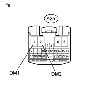 |
Disconnect the 4 wheel drive control ECU connector.
Measure the resistance according to the value(s) in the table below.
| Tester Connection | Condition | Specified Condition |
| A25-1 (DM1) - A25-2 (DM2) | Always | 0.5 Ω or higher |
| *a | Front view of wire harness connector (to 4 Wheel Drive Control ECU) |
|
| ||||
| OK | |
|
| 6.CHECK HARNESS AND CONNECTOR ( 4 WHEEL DRIVE CONTROL ECU - DIFFERENTIAL VACUUM ACTUATOR ASSEMBLY) |
Disconnect the A25 4 wheel drive control ECU connector.
Disconnect the G1 A.D.D. actuator (differential vacuum actuator assembly) connector.
Measure the resistance according to the value(s) in the table below.
| Tester Connection | Condition | Specified Condition |
| A25-1 (DM1) or G1-1 (DM1) - A25-2 (DM2) or G1-2 (DM2) | Always | 10 kΩ or higher |
|
| ||||
| OK | ||
| ||
| ||

