Home › Engine / Hybrid System › 3UR-FBE ENGINE CONTROL › SFI SYSTEM
RM27M0U _51 Engine / Hybrid System _049095 3UR-FBE ENGINE CONTROL _0233928 SFI SYSTEM C

3UR-FBE ENGINE CONTROL  SFI SYSTEM  P0412  Secondary Air Injection System Switching Valve "A" Circuit  P0415  Secondary Air Injection System Switching Valve "B" Circuit  


DESCRIPTION

The Secondary Air Injection (AIR) system consists of an air pump, the Air Switching Valve (ASV), a pressure sensor, the Air Injection Control Driver (AID) and the ECM. For a short time after cold engine starts, the AIR system pumps secondary air to the exhaust port of the cylinder head to purify the exhaust emissions. The secondary air is supplied by the air pump and is pumped to the exhaust port through the ASV.

The AID drives the ASV and the air pump according to command signals transmitted by the ECM. The pressure sensor detects the pressure in the secondary air passage when the AIR system is ON and OFF, and transmits a pressure signal to the ECM.

The AID is not only equipped to drive the pump and valve, but also with a diagnosis function to detect malfunctions in the AIR system circuit.

HINT:

As a large current is required to drive the air pump and ASV, an AID is installed to this system.
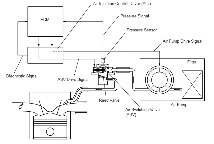

A162565E02
0.771,1.844 0.479,2.438 false 3.979,0.531 3.458,1.177 false 3.552,3.26 3.458,2.583 false 2.479,2.552 2.635,1.979 false 3.531,2.333 4.688,3.594 false 5.406,1.448 5.146,1.719 false 3.448,2.021 4.188,1.104 false 1.927,1.635 3.052,0.146 false 1.354,0.573 1.708,0.74 0.354,0.167 10 false ECM 3.115,0.031 5.135,0.24 2.021,0.208 10 false Air Injection Control Driver (AID) 0.208,2.458 1.385,2.656 1.177,0.198 10 false Diagnostic Signal 4.031,0.448 5.083,0.635 1.052,0.188 10 false Pressure Signal 3.313,3.271 4.083,3.448 0.771,0.177 10 false Reed Valve 1.927,2.573 3.042,2.76 1.115,0.188 10 false ASV Drive Signal 4.198,3.583 5.417,3.948 1.219,0.365 10 false Air Switching Valve (ASV) 5.719,3.417 6.417,3.646 0.698,0.229 10 false Air Pump 6.271,1.99 6.635,2.177 0.365,0.188 10 false Filter 5.448,1.292 6.875,1.49 1.427,0.198 10 false Air Pump Drive Signal 4.24,0.917 5.365,1.125 1.125,0.208 10 false Pressure Sensor

DTC No. DTC Detection Condition Trouble Area
P0412
P0415

After cold engine starts, all of following conditions met (1 trip detection logic):

1.

Secondary Air Injection (AIR) system not operating (air pump OFF, Air Switching Valve [ASV] OFF)

2.

Diagnostic signal from Air Injection Control Driver (AID) 40%

3.

Battery voltage 8 V or more


·

Open in ASV drive circuit

·

AID

·

ASV

·

ECM


P0412
P0415

After cold engine starts, all of following conditions met (1 trip detection logic):

1.

Secondary Air Injection (AIR) system operating (air pump ON, Air Switching Valve [ASV] ON)

2.

Diagnostic signal from Air Injection Control Driver (AID) 40%

3.

Battery voltage 8 V or more


·

Short between ASV drive circuit and body ground

·

AID

·

ASV

·

ECM


MONITOR DESCRIPTION

The Air Injection Control Driver (AID) detects open and short circuits according to the voltages of the air pump terminal (VP) and the Air Switching Valve (ASV) terminal (VV), and transmits diagnostic information as a signal to the ECM.

For a short time after cold engine starts, the ECM transmits command signals to the AID to drive the air pump and ASV.

The AID transmits an ASV malfunction signal to the ECM if either of the following conditions is met:

·

The voltage at the AID terminal relating to the ASV is low despite the AID receiving command signals from the ECM to drive the ASV.

·

The voltage at the AID terminal relating to the ASV is high despite the AID receiving no command signals from the ECM to drive the ASV.


The ECM stores the DTC based on diagnostic signals from the AID.

MONITOR STRATEGY

Related DTCs P0412: Secondary air injection system air switching valve circuit range check (Bank 1)
P0415: Secondary air injection system air switching valve circuit range check (Bank 2)
Required Sensors/Components (Main) Air injection control driver
Required Sensors/Components (Related) Air switching valve
Frequency of Operation Once per drive cycle
Duration 3 seconds
MIL Operation Immediate
Sequence of Operation None

TYPICAL ENABLING CONDITIONS

Case 1:
Monitor runs whenever following DTCs not stored -
Secondary air injection pump Operating
Secondary air injection switching valve Operating
Battery voltage 8 V or more
Ignition switch ON
Starter OFF

Case 2:
Monitor runs whenever following DTCs not stored -
Secondary air injection pump Not operating
Secondary air injection switching valve Not operating
Battery voltage 8 V or more
Ignition switch ON
Starter OFF

TYPICAL MALFUNCTION THRESHOLDS

Diagnostic signal duty ratio from air injection control driver 31% or more, and 48% or less

COMPONENT OPERATING RANGE

Diagnostic signal duty ratio from air injection control driver 70% or more, and 90% or less when secondary air injection system operating.
0% when secondary air injection system not operating.

CONFIRMATION DRIVING PATTERN

NOTICE:
·

This Secondary Air Injection Check only allows technicians to operate the AIR system for a maximum of 5 seconds.

Furthermore, the check can only be performed up to 4 times per trip. If the test is repeated, intervals of at least 30 seconds are required between checks.

While AIR system operation using the Techstream is prohibited, the Techstream display indicates the prohibition (WAIT or ERROR).

If ERROR is displayed on the Techstream during the test, stop the engine for 10 minutes, and then try again.

·

Performing the Secondary Air Injection Check repeatedly may cause damage to the AIR system. If necessary, leave an interval of several minutes between System Check operations to prevent the system from overheating.

·

When performing the Secondary Air Injection Check operation after the battery cable has been reconnected, wait for 7 minutes with the ignition switch turned to ON or the engine running.

·

Turn the ignition switch off when the Secondary Air Injection Check operation finishes.


1.

Start the engine and warm it up.

2.

Turn the ignition switch off.

3.

Connect the Techstream to the DLC3.

4.

Turn the ignition switch to ON.

5.

Turn the Techstream on.

7.

Turn the ignition switch off and wait for at least 30 seconds.

8.

Turn the ignition switch to ON and turn the Techstream on.

9.

Enter the following menus: Powertrain / Engine and ECT / Utility / Secondary Air Injection Check / Automatic Mode.

10.

Start the engine after the Techstream initialization is finished.

11.

Perform the System Check operation by pressing ENTER (Next).

12.

Perform the following to confirm the AIR system pending codes: Press ENTER (Exit).

13.

Check for pending DTCs.

OK:

No pending DTC is output.


14.

After the "Secondary Air Injection Check" is completed, check for All Readiness by entering the following menus: Powertrain / Engine and ECT / Utility / All Readiness.

15.

Input the DTC: P0412 or P0415.

16.

Check the DTC judgment result.

Tester Display Description
NORMAL
·

DTC judgment completed

·

System normal


ABNORMAL
·

DTC judgment completed

·

System abnormal


INCOMPLETE
·

DTC judgment not completed

·

Perform driving pattern after confirming DTC enabling conditions


N/A
·

Unable to perform DTC judgment

·

Number of DTCs which do not fulfill DTC preconditions has reached ECU memory limit


HINT:
·

If the judgment result shows NORMAL, the system is normal.

·

If the judgment result shows ABNORMAL, the system has a malfunction.


17.

If the test result is INCOMPLETE or N/A and no pending DTC is output, perform a universal trip and check for permanent DTCs (See page Engine / Hybrid System>3UR-FBE ENGINE CONTROL>SFI SYSTEM>DTC CHECK / CLEAR).

HINT:
·

If no permanent DTC is output, the system is normal.

·

If a permanent DTC is output, the system is malfunctioning.


18.

Turn the ignition switch off.


WIRING DIAGRAM
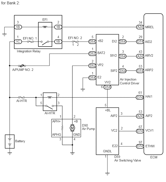
A258961E29
6.271,1.042 6.698,1.198 0.427,0.156 10 false MREL 6.26,1.677 6.563,1.833 0.302,0.156 10 false AIDI 6.26,2.313 6.625,2.469 0.365,0.156 10 false AIRV 6.26,2.938 6.625,3.094 0.365,0.156 10 false AIRP 6.26,4.917 6.531,5.073 0.271,0.156 10 false AIP 6.26,5.552 6.667,5.708 0.406,0.156 10 false VCV1 4.823,4.917 5.094,5.073 0.271,0.156 10 false AIP 4.854,5.552 5.125,5.708 0.271,0.156 10 false VC 4.885,6.219 5.125,6.375 0.24,0.156 10 false E2 4.49,6.448 4.917,6.604 0.427,0.156 10 false GND 6.26,6.229 6.677,6.385 0.417,0.156 10 false ETHA 5.927,1.083 6.271,1.26 0.344,0.177 10 false A24 5.938,1.708 6.281,1.885 0.344,0.177 10 false D74 5.927,4.927 6.219,5.083 0.292,0.156 10 false A24 5.927,5.583 6.25,5.74 0.323,0.156 10 false D74 5.917,6.24 6.208,6.396 0.292,0.156 10 false D74 5.927,2.344 6.271,2.531 0.344,0.188 10 false D74 5.917,2.969 6.229,3.146 0.313,0.177 10 false D74 6.49,6.698 6.865,6.885 0.375,0.188 10 false ECM 5.99,6.063 6.188,6.219 0.198,0.156 10 false 98 5.99,5.396 6.188,5.552 0.198,0.156 10 false 67 5.99,4.74 6.188,4.896 0.198,0.156 10 false 54 5.99,2.781 6.188,2.938 0.198,0.156 10 false 54 5.99,2.146 6.188,2.302 0.198,0.156 10 false 28 5.99,1.51 6.188,1.667 0.198,0.156 10 false 30 5.99,0.885 6.188,1.042 0.198,0.156 10 false 34 5.167,1.708 5.49,1.875 0.323,0.167 10 false D50 3.875,1.708 4.188,1.875 0.313,0.167 10 false D50 3.865,3.271 4.167,3.427 0.302,0.156 10 false D50 3.865,2.75 4.167,2.938 0.302,0.188 10 false D48 3.865,2.24 4.177,2.417 0.313,0.177 10 false D48 4.521,3.677 4.823,3.844 0.302,0.167 10 false D50 5.167,2.344 5.469,2.5 0.302,0.156 10 false D50 5.167,2.979 5.479,3.146 0.313,0.167 10 false D50 5.271,1.51 5.385,1.667 0.115,0.156 10 false 2 3.958,1.51 4.073,1.667 0.115,0.156 10 false 5 3.958,2.031 4.073,2.188 0.115,0.156 10 false 1 3.115,1.833 3.229,1.99 0.115,0.156 10 false 1 3.323,1.833 3.438,1.99 0.115,0.156 10 false 2 2.479,0.875 2.594,1.031 0.115,0.156 10 false 2 3.958,2.563 4.073,2.719 0.115,0.156 10 false 2 4.344,3.677 4.458,3.833 0.115,0.156 10 false 6 4.938,6.688 5.219,6.844 0.281,0.156 10 false D58 4.521,4.458 4.635,4.615 0.115,0.156 10 false 5 5.208,4.823 5.323,4.979 0.115,0.156 10 false 3 5.219,5.458 5.333,5.615 0.115,0.156 10 false 2 5.208,6.125 5.323,6.281 0.115,0.156 10 false 4 4.521,6.677 4.635,6.833 0.115,0.156 10 false 1 3.958,3.083 4.073,3.24 0.115,0.156 10 false 1 5.271,2.146 5.385,2.302 0.115,0.156 10 false 3 5.271,2.781 5.385,2.938 0.115,0.156 10 false 4 4.938,1.677 5.125,1.833 0.188,0.156 10 false DI 4.875,2.323 5.125,2.479 0.25,0.156 10 false SIV 4.844,2.938 5.104,3.094 0.26,0.156 10 false SIP 4.563,3.469 4.823,3.625 0.26,0.156 10 false VV 4.208,1.677 4.417,1.833 0.208,0.156 10 false +B 4.208,2.198 4.594,2.354 0.385,0.156 10 false BATT 4.208,2.719 4.438,2.875 0.229,0.156 10 false VP 4.208,3.25 4.354,3.406 0.146,0.156 10 false E 5.177,3.344 6.083,3.677 0.906,0.333 10 false Air Injection Control Driver 4.938,6.844 6.156,7.021 1.219,0.177 10 false Air Switching Valve 3.542,5.333 3.823,5.5 0.281,0.167 10 false D89 3.542,5.479 4.146,5.677 0.604,0.198 10 false Air Pump 3.177,4.948 3.292,5.115 0.115,0.167 10 false 2 2.563,4.948 2.677,5.115 0.115,0.167 10 false 1 2.938,1.552 3.594,1.729 0.656,0.177 10 false EFI NO. 2 2.427,1.073 2.698,1.25 0.271,0.177 10 false 1B 2.479,1.51 2.594,1.667 0.115,0.156 10 false 4 2.438,1.708 2.677,1.875 0.24,0.167 10 false 1B 0.729,0.875 0.844,1.031 0.115,0.156 10 false 3 0.688,1.083 0.927,1.271 0.24,0.188 10 false 1B 0.729,1.51 0.844,1.667 0.115,0.156 10 false 1 0.688,1.708 0.938,1.875 0.25,0.167 10 false 1C 0.729,2.125 1.833,2.313 1.104,0.188 10 false Integration Relay 1.833,0.76 2.094,0.917 0.26,0.156 10 false EFI 0.99,1.573 1.646,1.729 0.656,0.156 10 false EFI NO. 1 0.531,2.927 1.479,3.094 0.948,0.167 10 false A/PUMP NO. 1 0.656,6.01 1.135,6.188 0.479,0.177 10 false Battery 0.052,0.021 0.917,0.219 0.865,0.198 12 false for Bank 1: 4.552,4.677 4.792,4.833 0.24,0.156 10 false +B 5.906,4.115 6.198,4.271 0.292,0.156 10 false D74 5.969,3.938 6.188,4.104 0.219,0.167 10 false 61 0.698,4.271 1.25,4.438 0.552,0.167 10 false AI-HTR 6.281,4.083 6.646,4.26 0.365,0.177 10 false HAI1 2.552,5.917 2.667,6.083 0.115,0.167 10 false 3 1.74,4.365 1.854,4.531 0.115,0.167 10 false 5 1.74,4.021 1.854,4.188 0.115,0.167 10 false 1 2.49,4.365 2.604,4.531 0.115,0.167 10 false 3 2.49,4.021 2.604,4.188 0.115,0.167 10 false 2 3.177,5.927 3.292,6.094 0.115,0.167 10 false 4 3.188,5.729 3.302,5.896 0.115,0.167 10 false E 2.26,5.729 2.719,5.896 0.458,0.167 10 false APHG 3.188,5.167 3.375,5.365 0.188,0.198 10 false B 2.25,5.167 2.698,5.365 0.448,0.198 10 false APH+ 1.927,4.792 2.417,4.979 0.49,0.188 10 false AI-HTR

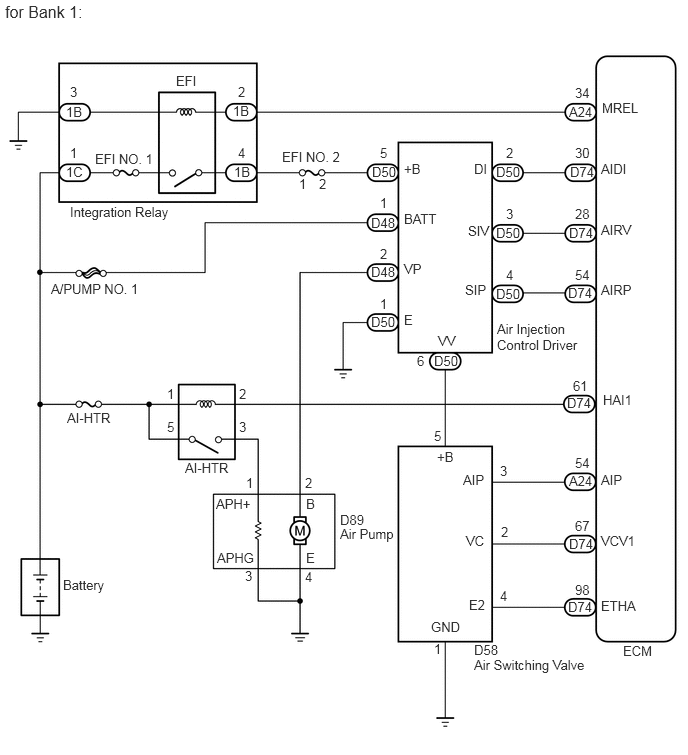
A258961E30
6.271,1.083 6.74,1.26 0.469,0.177 10 false MREL 6.26,1.719 6.635,1.885 0.375,0.167 10 false AID2 6.26,2.313 6.656,2.469 0.396,0.156 10 false ARV2 6.26,2.938 6.688,3.094 0.427,0.156 10 false ARP2 6.281,4.917 6.656,5.073 0.375,0.156 10 false AIP2 6.281,5.552 6.688,5.708 0.406,0.156 10 false VCV1 4.771,4.917 5.115,5.073 0.344,0.156 10 false AIP2 4.802,5.552 5.104,5.708 0.302,0.156 10 false VC2 4.844,6.219 5.115,6.375 0.271,0.156 10 false E22 4.448,6.448 4.938,6.604 0.49,0.156 10 false GNDL 6.281,6.229 6.729,6.385 0.448,0.156 10 false ETHW 5.927,1.073 6.25,1.24 0.323,0.167 10 false A24 5.927,1.708 6.24,1.885 0.313,0.177 10 false D74 5.917,4.927 6.24,5.104 0.323,0.177 10 false A24 5.917,5.573 6.208,5.729 0.292,0.156 10 false D74 5.917,6.229 6.208,6.385 0.292,0.156 10 false D74 5.927,2.344 6.24,2.51 0.313,0.167 10 false A24 5.927,2.979 6.25,3.146 0.323,0.167 10 false D74 6.49,6.708 6.896,6.896 0.406,0.188 10 false ECM 5.99,6.063 6.188,6.219 0.198,0.156 10 false 97 5.99,5.396 6.188,5.552 0.198,0.156 10 false 67 5.99,4.74 6.188,4.896 0.198,0.156 10 false 53 5.99,2.781 6.188,2.938 0.198,0.156 10 false 53 5.99,2.146 6.188,2.302 0.198,0.156 10 false 43 5.99,1.51 6.188,1.667 0.198,0.156 10 false 29 5.99,0.885 6.188,1.042 0.198,0.156 10 false 34 5.167,1.708 5.521,1.885 0.354,0.177 10 false D54 3.865,1.708 4.167,1.865 0.302,0.156 10 false D54 3.865,3.271 4.198,3.458 0.333,0.188 10 false D54 3.875,2.75 4.208,2.938 0.333,0.188 10 false D52 3.865,2.229 4.188,2.417 0.323,0.188 10 false D52 4.521,3.667 4.833,3.844 0.313,0.177 10 false D54 5.167,2.344 5.5,2.51 0.333,0.167 10 false D54 5.177,2.979 5.49,3.156 0.313,0.177 10 false D54 5.271,1.51 5.385,1.667 0.115,0.156 10 false 2 3.958,1.51 4.073,1.667 0.115,0.156 10 false 5 3.958,2.031 4.073,2.188 0.115,0.156 10 false 1 3.115,1.844 3.229,2 0.115,0.156 10 false 1 3.323,1.844 3.438,2 0.115,0.156 10 false 2 2.479,0.875 2.594,1.031 0.115,0.156 10 false 2 3.958,2.563 4.073,2.719 0.115,0.156 10 false 2 4.365,3.667 4.479,3.823 0.115,0.156 10 false 6 4.938,6.688 5.219,6.844 0.281,0.156 10 false D59 4.521,4.458 4.635,4.615 0.115,0.156 10 false 5 5.208,4.823 5.323,4.979 0.115,0.156 10 false 3 5.219,5.458 5.333,5.615 0.115,0.156 10 false 2 5.208,6.125 5.323,6.281 0.115,0.156 10 false 4 4.521,6.677 4.635,6.833 0.115,0.156 10 false 1 3.958,3.083 4.073,3.24 0.115,0.156 10 false 1 5.271,2.146 5.385,2.302 0.115,0.156 10 false 3 5.271,2.781 5.385,2.938 0.115,0.156 10 false 4 4.833,1.698 5.115,1.875 0.281,0.177 10 false DI2 4.75,2.313 5.115,2.469 0.365,0.156 10 false SIV2 4.771,2.969 5.125,3.156 0.354,0.188 10 false SIP2 4.521,3.469 4.823,3.625 0.302,0.156 10 false VV2 4.208,1.677 4.49,1.833 0.281,0.156 10 false +B2 4.208,2.198 4.594,2.354 0.385,0.156 10 false BAT2 4.208,2.719 4.5,2.875 0.292,0.156 10 false VP2 4.208,3.25 4.438,3.406 0.229,0.156 10 false E2 5.177,3.344 6.083,3.677 0.906,0.333 10 false Air Injection Control Driver 4.938,6.844 6.156,7.021 1.219,0.177 10 false Air Switching Valve 3.542,5.333 3.823,5.5 0.281,0.167 10 false D90 3.542,5.479 4.146,5.677 0.604,0.198 10 false Air Pump 3.177,4.948 3.292,5.115 0.115,0.167 10 false 2 2.573,4.948 2.688,5.115 0.115,0.167 10 false 1 2.938,1.552 3.594,1.729 0.656,0.177 10 false EFI NO. 2 2.427,1.083 2.677,1.26 0.25,0.177 10 false 1B 2.479,1.51 2.594,1.667 0.115,0.156 10 false 4 2.417,1.708 2.698,1.885 0.281,0.177 10 false 1B 0.729,0.875 0.844,1.031 0.115,0.156 10 false 3 0.688,1.083 0.927,1.26 0.24,0.177 10 false 1B 0.729,1.51 0.844,1.667 0.115,0.156 10 false 1 0.688,1.708 0.927,1.896 0.24,0.188 10 false 1C 0.729,2.125 1.833,2.313 1.104,0.188 10 false Integration Relay 1.833,0.76 2.094,0.917 0.26,0.156 10 false EFI 0.99,1.573 1.646,1.729 0.656,0.156 10 false EFI NO. 1 0.531,2.927 1.479,3.094 0.948,0.167 10 false A/PUMP NO. 2 0.656,6.01 1.135,6.188 0.479,0.177 10 false Battery 0.052,0.021 0.917,0.219 0.865,0.198 12 false for Bank 2: 4.531,4.677 4.823,4.833 0.292,0.156 10 false +BL 5.917,4.125 6.24,4.281 0.323,0.156 10 false D74 5.979,3.917 6.156,4.063 0.177,0.146 10 false 61 0.708,4.271 1.25,4.438 0.542,0.167 10 false AI-HTR 6.281,4.083 6.646,4.26 0.365,0.177 10 false HAI1 2.563,5.927 2.677,6.094 0.115,0.167 10 false 3 1.74,4.365 1.854,4.531 0.115,0.167 10 false 5 1.74,4.021 1.854,4.188 0.115,0.167 10 false 1 2.49,4.365 2.604,4.531 0.115,0.167 10 false 3 2.49,4.021 2.604,4.188 0.115,0.167 10 false 2 3.177,5.927 3.292,6.094 0.115,0.167 10 false 4 3.156,5.729 3.49,5.896 0.333,0.167 10 false GND 2.25,5.729 2.708,5.896 0.458,0.167 10 false APHG 3.188,5.156 3.458,5.333 0.271,0.177 10 false +B 2.26,5.156 2.729,5.333 0.469,0.177 10 false APH+ 1.927,4.802 2.427,5.01 0.5,0.208 10 false AI-HTR

CAUTION / NOTICE / HINT

NOTICE:

Inspect the fuses for circuits related to this system before performing the following procedure.


HINT:
·

By using the Techstream to perform the Secondary Air Injection Check operation in the System Check, the air-fuel ratio and the pressure in the secondary air injection system passage can be checked while the secondary air injection system is operating. This helps technicians to troubleshoot the system when it malfunctions.

·

Read freeze frame data using the Techstream. Freeze frame data records the engine condition when malfunctions are detected. When troubleshooting, freeze frame data can help determine if the vehicle was moving or stationary, if the engine was warmed up or not, if the air-fuel ratio was lean or rich, and other data from the time the malfunction occurred.

·

Bank 1 refers to the bank that includes the No. 1 cylinder*.

*: The No. 1 cylinder is the cylinder which is farthest from the transmission.

·

Bank 2 refers to the bank that does not include the No. 1 cylinder.


PROCEDURE

1.INSPECT AIR SWITCHING VALVE ASSEMBLY
a.

Inspect the air switching valve assembly (for bank 1) (See page Engine / Hybrid System>3UR-FBE EMISSION CONTROL>AIR SWITCHING VALVE>INSPECTION).


b.

Inspect the air switching valve assembly (for bank 2) (See page Engine / Hybrid System>3UR-FBE EMISSION CONTROL>AIR SWITCHING VALVE>INSPECTION).

Result
Result Proceed to
OK A
NG B


A

2.CHECK HARNESS AND CONNECTOR (AIR SWITCHING VALVE ASSEMBLY - BODY GROUND)

B

2.CHECK HARNESS AND CONNECTOR (AIR SWITCHING VALVE ASSEMBLY - BODY GROUND)
a.

Disconnect the D58 or D59 ASV connector.


b.

Measure the resistance according to the value(s) in the table below.

Standard resistance:
Tester Connection Condition Specified Condition
D58-1 (GND) - Body ground Always Below 1 Ω
D59-1 (GNDL) - Body ground Always Below 1 Ω


OK

3.CHECK HARNESS AND CONNECTOR (AIR SWITCHING VALVE ASSEMBLY - AIR INJECTION CONTROL DRIVER)

NG

REPAIR OR REPLACE HARNESS OR CONNECTOR

3.CHECK HARNESS AND CONNECTOR (AIR SWITCHING VALVE ASSEMBLY - AIR INJECTION CONTROL DRIVER)
a.

Disconnect the D58 or D59 ASV connector.


b.

Disconnect the D50 or D54 AID connector.


c.

Measure the resistance according to the value(s) in the table below.

Standard resistance:
Tester Connection Condition Specified Condition
D58-5 (+B) - D50-6 (VV) Always Below 1 Ω
D59-5 (+BL) - D54-6 (VV2) Always Below 1 Ω
D58-5 (+B) or D50-6 (VV) - Body ground Always 10 kΩ or higher
D59-5 (+BL) or D54-6 (VV2) - Body ground Always 10 kΩ or higher


OK

NG

REPAIR OR REPLACE HARNESS OR CONNECTOR