Home › Engine / Hybrid System › 3UR-FBE FUEL › FUEL SENDER GAUGE ASSEMBLY
RM27M0U _51 Engine / Hybrid System _049096 3UR-FBE FUEL _0233954 FUEL SENDER GAUGE ASSEMBLY A

3UR-FBE FUEL  FUEL SENDER GAUGE ASSEMBLY  INSTALLATION  


PROCEDURE

Hide 83320 1.INSTALL FUEL SENDER GAUGE ASSEMBLY
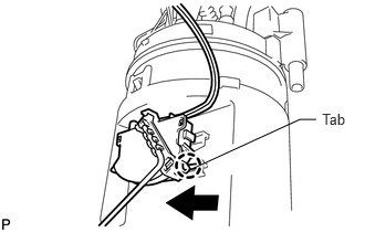
a.
A201439E01
3.032,1.044 3.331,1.256 0.299,0.211 10 Tab 1.817,1.588 2.823,1.126 2.823,1.126 2.977,1.126 false

Slide the fuel sender gauge onto the fuel suction support to install it.
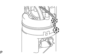

b.
A201437

Attach the 2 claws to connect the wire harness.
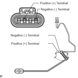

c.
A194662E01
1.762,0.048 3.088,0.261 1.326,0.213 10 Positive (+) Terminal 1.795,0.32 3.140,0.540 1.346,0.221 10 Negative (-) Terminal 1.09,0.779 1.483,0.136 1.483,0.136 1.71,0.136 false 1.6,0.775 1.657,0.4 1.657,0.4 1.757,0.4 false 0.496,1.83 1.855,2.040 1.358,0.210 10 Positive (+) Terminal 0.468,1.464 1.835,1.685 1.367,0.221 10 Negative (-) Terminal 2.124,1.915 2.319,1.915 2.319,1.915 2.545,2.254 false 2.115,1.554 2.413,1.554 2.413,1.554 2.628,2.255 false

Insert the 2 wire terminals into the connector.

NOTICE:
·

When inserting the wire terminals into the connector, be sure to insert the positive (+) terminal and negative (-) terminal into the correct locations.

·

Be careful not to deform the terminals.
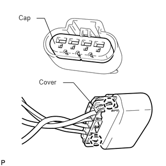


d.
A194661E01
0.383,0.279 0.706,0.500 0.323,0.221 10 Cap 0.804,1.617 1.259,1.835 0.455,0.218 10 Cover 0.758,0.377 0.921,0.377 0.921,0.377 1.137,0.91 false 1.306,1.711 1.522,1.711 1.522,1.711 1.97,2.23 false

Attach the 2 claws to install the cover to the back end of the connector, and then install the cap.
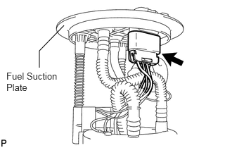

e.
A194625E02
0.583,1 0.583,0.75 0.583,0.75 0.948,0.375 false 0.094,1.042 0.948,1.51 0.854,0.469 10 false Fuel Suction Plate

Connect the connector to the fuel suction plate.


Hide 77020A 2.INSTALL FUEL SUCTION WITH PUMP AND GAUGE TUBE ASSEMBLY

a.

Install the fuel suction with pump and gauge tube assembly (See page Engine / Hybrid System>3UR-FBE FUEL>FUEL PUMP>INSTALLATION).