3UR-FE FUEL FUEL TANK INSTALLATION
PROCEDURE

 77641A
1.INSTALL NO. 1 FUEL TANK PROTECTOR (w/ Cover)
- HINT:
-
Only perform this procedure when replacement of the No. 1 fuel tank protector is necessary.
Attach the 4 clamps to install a new No. 1 fuel tank protector.
77020A
2.INSTALL FUEL SUCTION WITH PUMP AND GAUGE TUBE ASSEMBLY
Apply a light coat of gasoline to a new gasket, and install it to the fuel tank assembly.
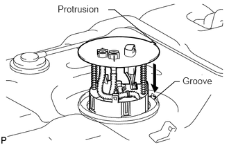
Align the protrusion of the pump and gauge tube with the groove of the fuel tank assembly.
Install the fuel suction with pump and gauge tube into the fuel tank assembly.
- NOTICE:
-
Be careful not to bend the arm of the fuel sender gauge.
Put the retainer on the fuel tank assembly. While holding the fuel suction with pump and gauge tube, tighten the retainer one complete turn by hand.
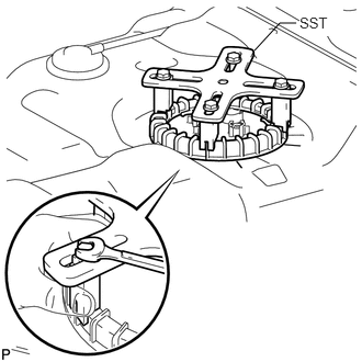
Set SST on the retainer.
- SST
- 09808-14030
- HINT:
- ·
Hold the fuel suction tube assembly upright by hand to ensure that the fuel suction tube gasket is not moved out of position.
·Securely attach the claws of SST to the protrusions of the retainer and fix SST in place.
·Install SST while pressing the claws of SST against the retainer (toward the center of SST).
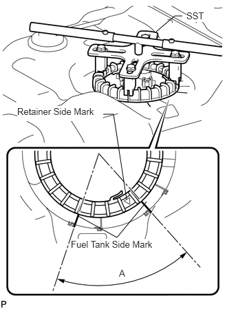
Using SST, tighten the retainer until the mark on the retainer is within range A on the fuel tank assembly as shown in the illustration.
- SST
- 09808-14030
- HINT:
-
Fit the tips of SST onto the ribs of the retainer.
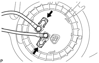
Install the fuel tank main tube sub-assembly and fuel tank return tube with the 2 tube joint clips.
- NOTICE:
-
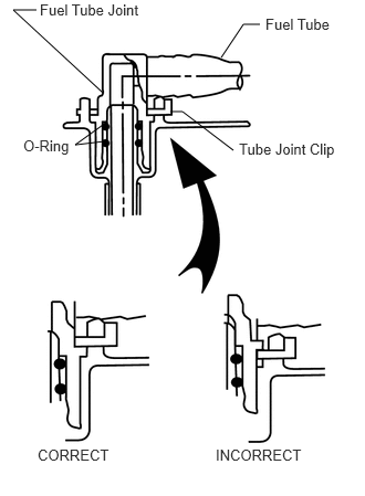 2.448,0.229 2.292,0.229 2.292,0.229 2.083,0.542 false 0.344,0.094 0.125,0.094 0.125,0.094 0.969,0.875 false 0.969,1.177 0.708,1.365 0.708,1.365 0.979,1.333 false 1.604,1.052 1.719,1.052 1.719,1.052 2.198,1.417 false 2.5,0.146 3.177,0.302 0.677,0.156 10 false Fuel Tube 0.375,0.01 1.438,0.188 1.063,0.177 10 false Fuel Tube Joint 0.219,1.292 0.792,1.521 0.573,0.229 10 false O-Ring 2.25,1.323 3.271,1.521 1.021,0.198 10 false Tube Joint Clip 0.354,4.208 1.104,4.396 0.75,0.188 10 false CORRECT 2.031,4.208 2.917,4.396 0.885,0.188 10 false INCORRECT
- ·
Check that there are no scratches or foreign objects on the connecting parts.
·Check that the fuel tube joints are inserted securely.
·Check that the tube joint clips are on the collars of the fuel tube joints.
·After installing the tube joint clips, check that the fuel tube joints have not been pulled off.
77213B
3.INSTALL FUEL TANK TO FILLER PIPE HOSE
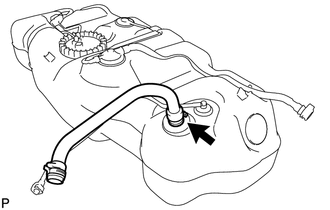
Install the fuel tank to filler pipe hose to the fuel tank assembly.
77697A
4.INSTALL NO. 2 FUEL TANK HEAT INSULATOR (for 144 L (38 US gal) Fuel Tank)
Install the No. 2 fuel tank heat insulator with the 3 clips.
77697
5.INSTALL NO. 1 FUEL TANK HEAT INSULATOR
for 100 L (26.4 US gal) Fuel Tank:
Install the No. 1 fuel tank heat insulator with the 4 clips and nut.
- Torque:
- 6.0 N*m (61 kgf*cm, 53 in.*lbf)
for 144 L (38 US gal) Fuel Tank:
Install the No. 1 fuel tank heat insulator with the 2 clips and 2 nuts.
- Torque:
- 6.0 N*m (61 kgf*cm, 53 in.*lbf)
77201
6.INSTALL INLET FUEL TANK PIPE SUB-ASSEMBLY
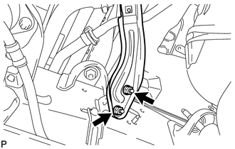
Install the inlet fuel tank pipe sub-assembly with the 2 nuts.
- Torque:
- 20 N*m (204 kgf*cm, 15 ft.*lbf)
77100
7.INSTALL FUEL TANK ASSEMBLY
Set the fuel tank assembly on an engine lifter and raise the fuel tank assembly.
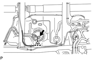
Connect the harness clamp and fuel pump connector to the fuel tank assembly.
- NOTICE:
-
Be careful not to cut the wiring.
w/ Cover:
Attach the 3 claws to install the No. 2 fuel tank protector.
Raise the engine lifter.
for 100 L (26.4 US gal) Fuel Tank:
Install the No. 1 fuel tank band sub-assembly and No. 2 fuel tank band sub-assembly with the 2 pins and 2 clips.
Connect the No. 1 fuel tank band sub-assembly and No. 2 fuel tank band sub-assembly with the 2 bolts.
- Torque:
- 40 N*m (408 kgf*cm, 30 ft.*lbf)
for 144 L (38 US gal) Fuel Tank:
Install the 2 No. 1 fuel tank band sub-assemblies and No. 2 fuel tank band sub-assembly with the 3 pins and 3 clips.
Connect the 2 No. 1 fuel tank band sub-assemblies and No. 2 fuel tank band sub-assembly with the 3 bolts.
- Torque:
- 40 N*m (408 kgf*cm, 30 ft.*lbf)
77754
8.CONNECT OUTLET NO. 1 CANISTER HOSE
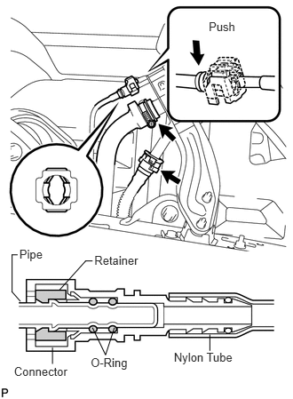
Connect the outlet No. 1 canister hose to the inlet fuel tank pipe sub-assembly.
Attach the hose to the No. 1 breather tube clamp.
77213B
9.CONNECT FUEL TANK TO FILLER PIPE HOSE
Connect the fuel tank to filler pipe hose to the inlet fuel tank pipe sub-assembly.
Connect the fuel tank breather tube to the inlet fuel tank pipe sub-assembly.
- NOTICE:
- ·
Before installing the tube connectors to the pipes, check if there is any damage or foreign matter in the connectors.
- ·
After the connection, check if the connectors and pipes are securely connected by trying to pull them apart.
- HINT:
-
Push the parts together firmly until a "click" sound is heard.
Attach the lock claws to the connector by pushing down on the cover as shown in the illustration.
Attach the filler pipe hose and fuel tank breather tube to the No. 1 breather tube clamp.
10.CONNECT WIRE HARNESS
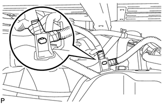
Attach the harness clamp to the fuel tank assembly.
11.CONNECT VENT LINE HOSE
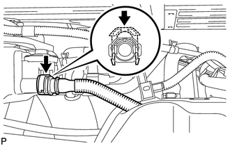
Connect the vent line hose and install the retainer.
- NOTICE:
- ·
Before installing the hose, make sure that it is not damaged. Make sure that there is no foreign matter present on the connecting surfaces.
- ·
After connecting, check if the hose and the connector are securely connected by pulling on them.
77204A
12.CONNECT FUEL TANK RETURN TUBE
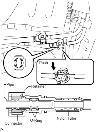
for 100 L (26.4 US gal) Fuel Tank:
Connect the fuel tank return tube.
- NOTICE:
- ·
Before installing the tube connectors to the pipes, check if there is any damage or foreign matter in the connectors.
- ·
After the connection, check if the connectors and pipes are securely connected by trying to pull them apart.
- HINT:
-
Push the parts together firmly until a "click" sound is heard.
Attach the lock claws to the connector by pushing down on the cover as shown in the illustration.
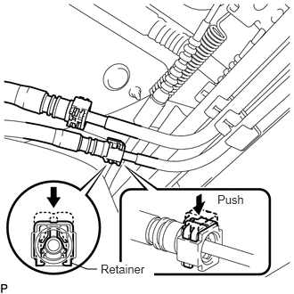
for 144 L (38 US gal) Fuel Tank:
Connect the fuel tank return tube.
- NOTICE:
- ·
Before installing the tube connectors to the pipes, check if there is any damage or foreign matter in the connectors.
- ·
After the connection, check if the connectors and pipes are securely connected by trying to pull them apart.
- HINT:
-
Push the parts together firmly until a "click" sound is heard.
Push down the retainer.
77209D
13.CONNECT FUEL TANK MAIN TUBE SUB-ASSEMBLY
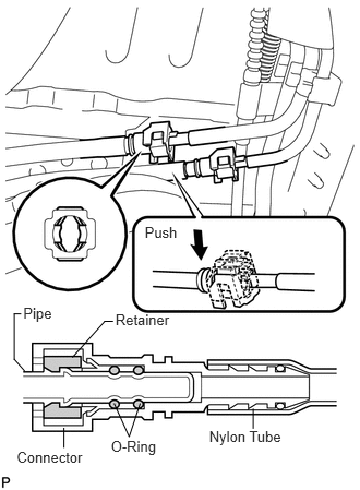
for 100 L (26.4 US gal) Fuel Tank:
Connect the fuel tank main tube.
- NOTICE:
- ·
Before installing the tube connectors to the pipes, check if there is any damage or foreign matter in the connectors.
- ·
After the connection, check if the connectors and pipes are securely connected by trying to pull them apart.
- HINT:
-
Push the parts together firmly until a "click" sound is heard.
Attach the lock claws to the connector by pushing down on the cover as shown in the illustration.
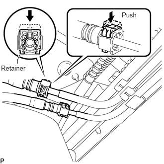
for 144 L (38 US gal) Fuel Tank:
Connect the fuel tank main tube.
- NOTICE:
- ·
Before installing the tube connectors to the pipes, check if there is any damage or foreign matter in the connectors.
- ·
After the connection, check if the connectors and pipes are securely connected by trying to pull them apart.
- HINT:
-
Push the parts together firmly until a "click" sound is heard.
Push down the retainer.
77606
14.INSTALL NO. 1 FUEL TANK PROTECTOR SUB-ASSEMBLY (for Rough Road Area Specification Vehicles)
for 100 L (26.4 US gal) Fuel Tank:
Install the No. 1 fuel tank protector sub-assembly with the 2 bolts and 2 nuts.
- Torque:
- for bolt : 29 N*m (296 kgf*cm, 21 ft.*lbf)
- for nut : 20 N*m (204 kgf*cm, 15 ft.*lbf)
for 144 L (38 US gal) Fuel Tank:
Install the No. 1 fuel tank protector sub-assembly with the 6 nuts.
- Torque:
- 20 N*m (204 kgf*cm, 15 ft.*lbf)
77310A
15.INSTALL FUEL TANK CAP
28800
16.CONNECT CABLE TO NEGATIVE BATTERY TERMINAL
17.INSPECT FOR FUEL LEAK