Home › Engine / Hybrid System › 3UR-FE EMISSION CONTROL › AIR PUMP
RM27M0U _51 Engine / Hybrid System _049100 3UR-FE EMISSION CONTROL _0233981 AIR PUMP A

3UR-FE EMISSION CONTROL  AIR PUMP  INSTALLATION  


PROCEDURE

Hide 17600C 1.INSTALL AIR PUMP ASSEMBLY

a.
A153467

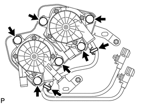
Connect the 6 air pump insulators to the 2 air pump assemblies and install the 2 air pump assemblies to the bracket.


b.

Attach the 2 wire harness clamps to the bracket.


Hide 17341 2.INSTALL NO. 1 AIR INJECTION SYSTEM HOSE
a.
U151447E02
0.99,0.5 1.104,0.5 1.104,0.5 1.313,0.938 false 1.281,1.229 1.396,1.229 1.396,1.229 1.521,1 false 0.333,0.396 0.875,0.573 0.542,0.177 10 false Stopper 0.573,1.125 1.156,1.281 0.583,0.156 10 false Air Hose

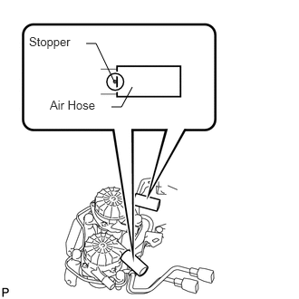
Install the 2 No. 1 air injection system hoses to the air pump.

HINT:

Insert the hoses until the hose ends are aligned with the stoppers.


Hide 17621A 3.INSTALL AIR PUMP INLET

a.
U151752E02
2.656,0.25 2.573,0.25 2.573,0.25 2.25,0.708 true 1.781,0.313 1.906,0.313 1.906,0.313 2.115,0.969 true 1.26,0.229 1.813,0.417 0.552,0.188 10 false Stopper 2.688,0.167 3.292,0.49 0.604,0.323 10 false Air Pump Inlet

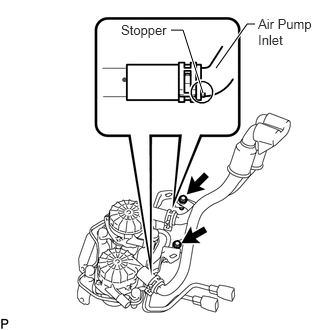
Connect the air pump inlet to the No. 1 air injection system hoses to install it, and then slide the 2 clips onto the hoses.

HINT:

Insert the inlet until the inlet stoppers are aligned with the hose ends.


b.

Install the 2 bolts.

Torque:
8.0 N*m (82 kgf*cm, 71 in.*lbf)


Hide 4.INSTALL AIR PUMP ASSEMBLY WITH BRACKET
a.
U151450E02
1.146,2.594 1.927,2.594 true 1.958,2.5 2.281,2.833 0.323,0.333 10 false Stud Bolt 1.073,3 1.229,3.167 0.156,0.167 10 false A 3.135,2.604 3.292,2.771 0.156,0.167 10 false B

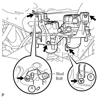
Install the air pump to the vehicle.

i.

Insert the bracket tab into the slot and insert the stud bolt into the bracket hole as shown in illustration A. Then slide the bracket.


ii.

Insert the bracket tab into the slot shown in illustration B.


iii.

Install the 2 bolts and 2 nuts.

Torque:
for bolt : 18 N*m (184 kgf*cm, 13 ft.*lbf)
for nut : 12 N*m (122 kgf*cm, 9 ft.*lbf)


b.
A158597

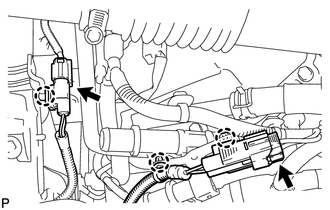
Connect the 2 air pump connectors and attach the 3 wire harness claws.


Hide 17343 5.INSTALL NO. 3 AIR INJECTION SYSTEM HOSE

a.

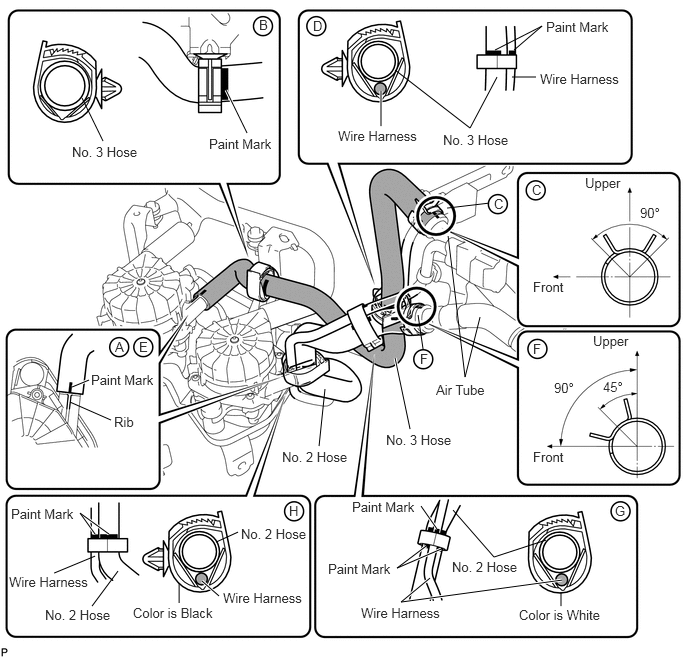
Connect the No. 3 hose so that its paint mark aligns with the air pump's rib as shown in the illustration below labeled A.


b.

Connect the clamp to the No. 3 hose shown in the illustration below labeled B. Then insert the clamp's clip into the body hole.

HINT:

Align the paint mark of the No. 3 hose with the edge of the clamp.


c.

Connect the No. 3 hose to the air tube shown in the illustration below labeled C.

HINT:
·

Make sure the paint mark of the No. 3 hose is facing upward.

·

Make sure the direction of the hose clamp is as shown in the illustration.


d.

Connect the clamp to the No. 3 hose and wire harness shown in the illustration below labeled D. Then insert the clamp's clip into the body hole.

HINT:

Align the paint mark of the No. 3 hose and paint mark of the wire harness with the edge of the clamp.


Hide 17342 6.INSTALL NO. 2 AIR INJECTION SYSTEM HOSE

a.

Connect the No. 2 hose so that its paint mark aligns with the air pump's rib as shown in the illustration below labeled E.


b.

Connect the No. 2 hose to the air tube shown in the illustration below labeled F.

HINT:
·

Make sure the paint mark of the No. 2 hose is facing upward.

·

Make sure the direction of the hose clamp is as shown in the illustration.


c.

Connect the white colored clamp to the No. 2 hose and wire harness shown in the illustration below labeled G.

HINT:
·

Make sure the paint mark of the No. 2 hose is facing upward.

·

Make sure the direction of the hose clamp is as shown in the illustration.


d.

Connect the black colored clamp to the No. 2 hose and wire harness shown in the illustration below labeled H. Then insert the clamp's clip into the body hole.
U151444E02
3.385,4.052 3.323,4.646 false 4.115,3.729 4.271,4.469 true 3.969,0.948 3.969,1.313 true 4.667,2.458 4.844,3.927 4.844,3.927 5,3.302 false 5.688,5.625 5.146,5.802 5.146,5.802 4.719,5.313 false 4.115,0.729 4.896,1.333 4.896,1.333 5.177,0.802 false 0.75,4.031 0.927,3.958 true 0.729,4.188 1.156,4.375 false 0.99,5.563 0.833,5.344 0.833,5.344 1.135,5.563 true 4.552,5.51 4.385,5.271 true 4.438,5.688 4.135,5.917 4.135,5.917 4.594,5.719 true 2.354,0.938 2.573,1.385 true 0.854,1.021 1.073,1.469 false 5.156,0.521 5.646,0.271 5.646,0.271 5.354,0.521 false 5.333,0.802 5.583,0.802 false 0.99,5.792 0.563,5.969 false 0.958,6.313 1.229,5.948 false 4.656,2.167 5.094,2.115 false 1.865,6.073 1.865,6.281 false 2.479,5.542 2.25,5.646 false 2.104,6.052 2.281,6.208 true 5.854,6.042 4.177,6.271 4.177,6.271 4.479,6.021 true 5.844,6.167 5.844,6.313 false 4.354,3.281 4.406,3.635 false 3.01,5.24 3.135,5.406 0.125,0.167 10 false H 6.406,5.24 6.563,5.406 0.156,0.167 10 false G 1.198,3.531 1.354,3.698 0.156,0.167 10 false A 1.448,3.531 1.604,3.698 0.156,0.167 10 false E 2.698,0.177 2.854,0.344 0.156,0.167 10 false B 4.542,3.979 5.125,4.135 0.583,0.156 10 false Air Tube 2.938,4.677 3.698,4.865 0.76,0.188 10 false No. 2 Hose 4.021,4.5 4.781,4.688 0.76,0.188 10 false No. 3 Hose 2.51,5.479 3.26,5.625 0.75,0.146 10 false No. 2 Hose 3.667,5.198 4.375,5.365 0.708,0.167 10 false Paint Mark 3.521,1.333 4.448,1.51 0.927,0.177 10 false Wire Harness 2.323,6.146 3.208,6.323 0.885,0.177 10 false Wire Harness 4.708,5.823 5.469,6.01 0.76,0.188 10 false No. 2 Hose 4.615,1.375 5.375,1.563 0.76,0.188 10 false No. 3 Hose 0.948,3.875 1.656,4.042 0.708,0.167 10 false Paint Mark 1.188,4.313 1.417,4.458 0.229,0.146 10 false Rib 0.115,5.271 0.823,5.438 0.708,0.167 10 false Paint Mark 3.417,5.844 4.125,6.01 0.708,0.167 10 false Paint Mark 6.094,1.823 6.51,2.01 0.417,0.188 10 false Upper 6.177,3.469 6.594,3.656 0.417,0.188 10 false Upper 5.552,2.906 5.917,3.063 0.365,0.156 10 false Front 5.552,4.677 5.917,4.833 0.365,0.156 10 false Front 5.771,3.958 6.031,4.125 0.26,0.167 10 false 90° 6.281,3.948 6.542,4.115 0.26,0.167 10 false 45° 6.667,2.135 6.927,2.302 0.26,0.167 10 false 90° 2.177,1.417 2.885,1.583 0.708,0.167 10 false Paint Mark 0.75,1.5 1.51,1.688 0.76,0.188 10 false No. 3 Hose 5.688,0.198 6.396,0.365 0.708,0.167 10 false Paint Mark 5.625,0.74 6.552,0.917 0.927,0.177 10 false Wire Harness 3.76,6.302 4.688,6.479 0.927,0.177 10 false Wire Harness 0.094,5.979 0.979,6.156 0.885,0.177 10 false Wire Harness 0.469,6.323 1.219,6.469 0.75,0.146 10 false No. 2 Hose 5.146,2.042 5.302,2.208 0.156,0.167 10 false C 5.542,1.896 5.698,2.063 0.156,0.167 10 false C 5.552,3.552 5.708,3.719 0.156,0.167 10 false F 3.26,0.188 3.417,0.354 0.156,0.167 10 false D 1.385,6.302 2.271,6.479 0.885,0.177 10 false Color is Black 5.406,6.323 6.313,6.51 0.906,0.188 10 false Color is White 4.375,3.656 4.531,3.823 0.156,0.167 10 false F


Hide 53736 7.CONNECT FRONT FENDER APRON SEAL RH
a.
A164869

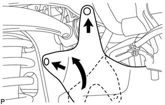
Connect the fender apron seal with the 2 clips.


Hide 8.CONNECT FRONT FENDER LINER RH