1UR-FE EMISSION CONTROL EGR VALVE INSTALLATION
PROCEDURE

 25625
1.INSTALL EGR VALVE BRACKET
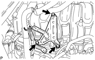
Install the EGR valve bracket with the 3 bolts.
- Torque:
- 21 N*m (214 kgf*cm, 15 ft.*lbf)
25603
2.INSTALL NO. 3 EGR PIPE SUB-ASSEMBLY
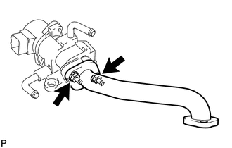
Install a new gasket and the No. 3 EGR pipe with the 2 nuts.
- Torque:
- 10 N*m (102 kgf*cm, 7 ft.*lbf)
25618
3.INSTALL EGR INLET
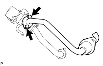
Install a new gasket and the EGR inlet with the 2 bolts.
- Torque:
- 10 N*m (102 kgf*cm, 7 ft.*lbf)
- NOTICE:
-
Make sure the gasket's claws are not caught between the EGR inlet and EGR valve.
25620
4.INSTALL EGR VALVE ASSEMBLY
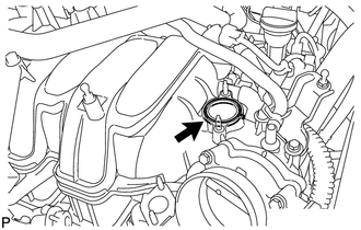
Install a new gasket to the intake manifold.
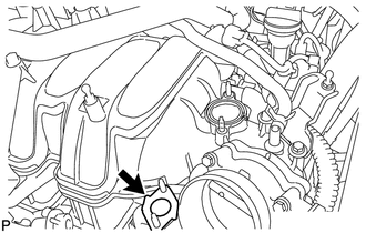
Install a new gasket to the No. 2 EGR pipe.
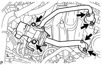
Temporarily install the EGR valve assembly to the intake manifold with the 2 bolts and 4 nuts.
- NOTICE:
-
Be careful not to damage the intake manifold when installing the EGR valve assembly.
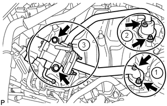
Using several steps, uniformly tighten the 2 bolts and 4 nuts in the sequence shown in the illustration.
- Torque:
- for bolt : 21 N*m (214 kgf*cm, 15 ft.*lbf)
- for nut : 10 N*m (102 kgf*cm, 7 ft.*lbf)
16261L
5.CONNECT NO. 13 WATER BY-PASS HOSE
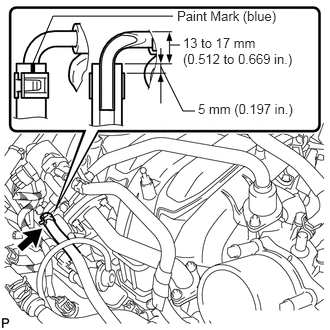
Connect the No. 13 water by-pass hose.
- HINT:
-
The direction of the hose clamp is indicated in the illustration.
16298
6.CONNECT NO. 12 WATER BY-PASS HOSE
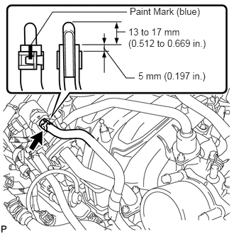
Connect the No. 12 water by-pass hose.
- HINT:
-
The direction of the hose clamp is indicated in the illustration.
17880
7.INSTALL AIR CLEANER HOSE ASSEMBLY
8.ADD ENGINE COOLANT
9.INSPECT FOR ENGINE COOLANT LEAK
11209
10.INSTALL V-BANK COVER SUB-ASSEMBLY