3UR-FE INTAKE VACUUM SWITCHING VALVE(for ACIS) ON-VEHICLE INSPECTION
PROCEDURE

 11209
1.REMOVE V-BANK COVER SUB-ASSEMBLY
17650
2.INSPECT VACUUM SWITCHING VALVE ASSEMBLY (for ACIS)
Disconnect the vacuum switching valve connector.
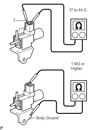
Measure the resistance according to the value(s) in the table below.
- Standard resistance:
Tester Condition Condition Specified Condition 1 - 2 20°C (68°F) 37 to 44 Ω 1 - Body ground Always 1 MΩ or higher 2 - Body ground
If the result is not as specified, replace the vacuum switching valve assembly.
Check the vacuum switching valve operation.
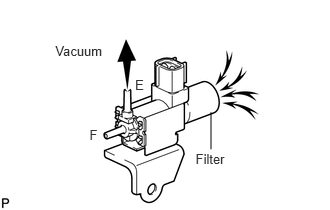
When applying a vacuum to port E, check that air is sucked into the filter.
If the result is not as specified, replace the vacuum switching valve assembly.
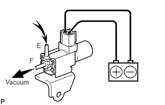
Apply voltage across the terminals.
When applying a vacuum to port F, check that air is sucked into port E.
If the result is not as specified, replace the vacuum switching valve assembly.
Connect the vacuum switching valve connector.
11209
3.INSTALL V-BANK COVER SUB-ASSEMBLY